CAN COMMUNICATION SYSTEM TERMINALS OF ECU

Tech Tips
Operating the ignition switch, any switches or any doors triggers related ECU and sensor communication with the CAN, which causes resistance variation.
-
DISCONNECT CABLE FROM NEGATIVE BATTERY TERMINAL
-
Disconnect the cable from the negative (-) battery terminal before measuring the resistances of the CAN main wire and the CAN branch wire.
CAUTION:
Wait at least 90 seconds after disconnecting the cable from the negative (-) battery terminal to disable the SRS system.
Note
-
Before measuring the resistance, leave the vehicle for at least 1 minute and do not operate the ignition switch, any switches or any doors. If doors need to be opened in order to check connectors, open the doors and leave them open.
-
After turning the ignition switch off, waiting time may be required before disconnecting the cable from the battery terminal. Therefore, make sure to read the disconnecting the cable from the battery terminal notice before proceeding with work Click here.
-
-
-
JUNCTION CONNECTOR
-
No. 1 Junction Connector
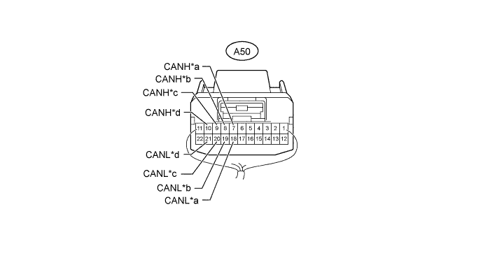
Text in Illustration *a for Engine Stop and Start ECU (w/ Stop and Start System) *b for Brake Actuator Assembly (Skid Control ECU) *c for No. 2 Junction Connector *d for ECM No. 1 Junction Connector Wiring Color Connect to A50-7 (CANH) P Engine stop and start ECU* A50-18 (CANL) W A50-8 (CANH) R Brake actuator assembly (skid control ECU) A50-19 (CANL) W A50-9 (CANH) B No. 2 junction connector A50-20 (CANL) W A50-10 (CANH) Y ECM A50-21 (CANL) W
-
*: w/ Stop and Start System
-
-
No. 2 Junction Connector
-
w/ Entry and Start System:
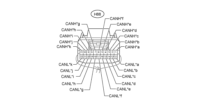
Text in Illustration *a for Power Management Control ECU *b for Certification ECU (Smart Key ECU Assembly) *c for Power Steering ECU Assembly *d for Radio and Display Receiver Assembly (for Radio and Display Type) *e for Spiral with Sensor Cable Sub-assembly (Steering Angle Sensor) *f for Yaw Rate Sensor *g for DLC3 *h for Main Body ECU (Instrument Panel Junction Block Assembly) *i for Combination Meter Assembly *j for No. 1 Junction Connector *k for Center Airbag Sensor Assembly - - No. 2 Junction Connector Wiring Color Connect to H88-1 (CANH) G Power management control ECU H88-12 (CANL) W H88-2 (CANH) SB Certification ECU (smart key ECU assembly) H88-13 (CANL) W H88-3 (CANH) SB Power steering ECU assembly H88-14 (CANL) W H88-4 (CANH) SB Radio and display receiver assembly* H88-15 (CANL) W H88-5 (CANH) BR Spiral with sensor cable sub-assembly (steering angle sensor) H88-16 (CANL) W H88-6 (CANH) L Yaw rate sensor H88-17 (CANL) W H88-7 (CANH) LG DLC3 H88-18 (CANL) W H88-8 (CANH) R Main body ECU (instrument panel junction block assembly) H88-19 (CANL) W H88-9 (CANH) SB Combination meter assembly H88-20 (CANL) W H88-10 (CANH) B No. 1 junction connector H88-21 (CANL) W H88-11 (CANH) Y Center airbag sensor assembly H88-22 (CANL) W
-
*: for Radio and Display Type
-
-
w/o Entry and Start System:
Text in Illustration *a for Driving Support ECU Assembly (for 1WW [w/ Cruise Control System]) *b for Air Conditioning Amplifier Assembly *c for Power Steering ECU Assembly *d for Radio and Display Receiver Assembly (for Radio and Display Type) *e for Spiral with Sensor Cable Sub-assembly (Steering Angle Sensor) *f for Yaw Rate Sensor *g for DLC3 *h for Main Body ECU (Instrument Panel Junction Block Assembly) *i for Combination Meter Assembly *j for No. 1 Junction Connector *k for Center Airbag Sensor Assembly - - No. 2 Junction Connector Wiring Color Connect to H88-1 (CANH) SB Driving support ECU assembly*1 H88-12 (CANL) W H88-2 (CANH) V Air conditioning amplifier assembly H88-13 (CANL) W H88-3 (CANH) SB Power steering ECU assembly H88-14 (CANL) W H88-4 (CANH) SB Radio and display receiver assembly*2 H88-15 (CANL) W H88-5 (CANH) BR Spiral with sensor cable sub-assembly (steering angle sensor) H88-16 (CANL) W H88-6 (CANH) L Yaw rate sensor H88-17 (CANL) W H88-7 (CANH) LG DLC3 H88-18 (CANL) W H88-8 (CANH) R Main body ECU (instrument panel junction block assembly) H88-19 (CANL) W H88-9 (CANH) SB Combination meter assembly H88-20 (CANL) W H88-10 (CANH) B No. 1 junction connector H88-21 (CANL) W H88-11 (CANH) Y Center airbag sensor assembly H88-22 (CANL) W
-
*1: for 1WW (w/ Cruise Control System)
-
*2: for Radio and Display Type
-
-
-
No. 3 Junction Connector
-
except 1WW (w/ Entry and Start System):
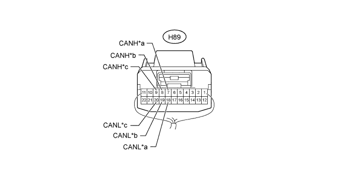
Text in Illustration *a for ECM *b for Power Management Control ECU *c for Air Conditioning Amplifier Assembly - - No. 3 Junction Connector Wiring Color Connect to H89-7 (CANH) R ECM H89-18 (CANL) W H89-8 (CANH) G Power management control ECU H89-19 (CANL) W H89-9 (CANH) V Air conditioning amplifier assembly H89-20 (CANL) W -
for 1WW (w/ Entry and Start System):
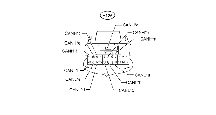
Text in Illustration *a for ECM *b for Power Management Control ECU (Power Management Bus) *c for Air Conditioning Amplifier Assembly *d for Driving Support ECU Assembly (for 1WW [w/ Cruise Control System]) *e for Power Management Control ECU (V2 Bus) *f for No. 4 Junction Connector No. 3 Junction Connector Wiring Color Connect to H126-5 (CANH) R ECM H126-16 (CANL) W H126-6 (CANH) G Power management control ECU (power management bus) H126-17 (CANL) W H126-7 (CANH) V Air conditioning amplifier assembly H126-18 (CANL) W H126-9 (CANH) L Driving support ECU assembly* H126-20 (CANL) W H126-10 (CANH) B Power management control ECU (V2 bus) H126-21 (CANL) W H126-11 (CANH) G No. 4 junction connector H126-22 (CANL) W
-
*: for 1WW (w/ Cruise Control System)
-
-
-
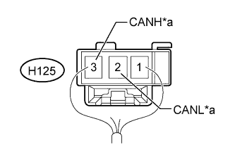
Text in Illustration *a for No. 3 Junction Connector No. 4 Junction Connector (for 1WW [w/ Entry and Start System])
No. 4 Junction Connector Wiring Color Connect to H125-2 (CANL) W No. 3 junction connector H125-3 (CANH) G
-
-
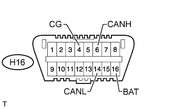
CHECK DLC3
-
Disconnect the cable from the negative (-) battery terminal before measuring the resistances of the CAN main wire and the CAN branch wire.
CAUTION:
Wait at least 90 seconds after disconnecting the cable from the negative (-) battery terminal to disable the SRS system.
Note
-
After turning the ignition switch off, waiting time may be required before disconnecting the cable from the battery terminal. Therefore, make sure to read the disconnecting the cable from the battery terminal notice before proceeding with work Click here.
-
When disconnecting the cable, some systems need to be initialized after the cable is reconnected Click here.
-
-
Measure the resistance according to the value(s) in the table below.
Terminal No. (Symbol) Wiring Color Switch Condition Specified Condition H16-6 (CANH) - H16-14 (CANL) LG - W Ignition switch off 54 to 69 Ω H16-6 (CANH) - H16-4 (CG) LG - W-B Ignition switch off 200 Ω or higher H16-14 (CANL) - H16-4 (CG) W - W-B Ignition switch off 200 Ω or higher H16-6 (CANH) - H16-16 (BAT) LG - G Ignition switch off 6 kΩ or higher H16-14 (CANL) - H16-16 (BAT) W - G Ignition switch off 6 kΩ or higher
-
-
CHECK ECM (for 1ZR-FAE, 2ZR-FAE)
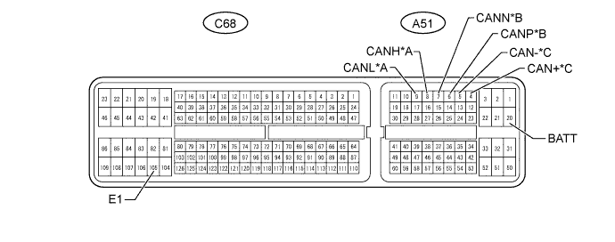
Text in Illustration *A for V1 Bus *B for Power Management Bus *C for Powertrain Bus - -
-
Disconnect the A51 and C68 ECM connectors.
-
Measure the resistance according to the value(s) in the table below.
for V1 Bus Terminal No. (Symbol) Wiring Color Switch Condition Specified Condition A51-8 (CANH) - A51-9 (CANL) Y - W Ignition switch off 108 to 132 Ω A51-8 (CANH) - C68-105 (E1) Y - BR Ignition switch off 200 Ω or higher A51-9 (CANL) - C68-105 (E1) W - BR Ignition switch off 200 Ω or higher A51-8 (CANH) - A51-20 (BATT) Y - P Ignition switch off 6 kΩ or higher A51-9 (CANL) - A51-20 (BATT) W - P Ignition switch off 6 kΩ or higher for Power Management Bus Terminal No. (Symbol) Wiring Color Switch Condition Specified Condition A51-6 (CANP) - A51-7 (CANN) R - W Ignition switch off 108 to 132 Ω A51-6 (CANP) - C68-105 (E1) R - BR Ignition switch off 200 Ω or higher A51-7 (CANN) - C68-105 (E1) W - BR Ignition switch off 200 Ω or higher A51-6 (CANP) - A51-20 (BATT) R - P Ignition switch off 6 kΩ or higher A51-7 (CANN) - A51-20 (BATT) W - P Ignition switch off 6 kΩ or higher for Powertrain Bus Terminal No. (Symbol) Wiring Color Switch Condition Specified Condition A51-4 (CAN+) - A51-5 (CAN-) Y - W Ignition switch off 108 to 132 Ω A51-4 (CAN+) - C68-105 (E1) Y - BR Ignition switch off 200 Ω or higher A51-5 (CAN-) - C68-105 (E1) W - BR Ignition switch off 200 Ω or higher A51-4 (CAN+) - A51-20 (BATT) Y - P Ignition switch off 6 kΩ or higher A51-5 (CAN-) - A51-20 (BATT) W - P Ignition switch off 6 kΩ or higher
-
-
CHECK ECM (for 1AD-FTV, 2AD-FHV)
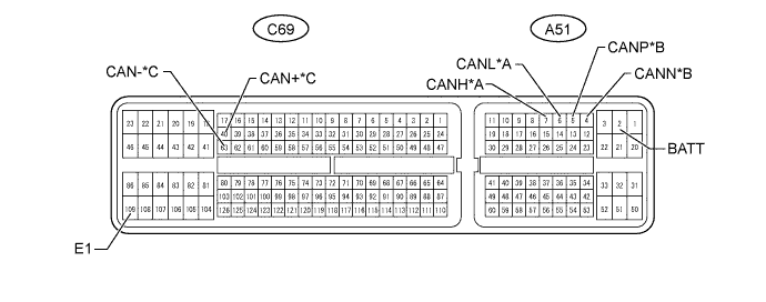
Text in Illustration *A for V1 Bus *B for Power Management Bus *C for Powertrain Bus - -
-
Disconnect the A51 and C69 ECM connectors.
-
Measure the resistance according to the value(s) in the table below.
for V1 Bus Terminal No. (Symbol) Wiring Color Switch Condition Specified Condition A51-7 (CANH) - A51-6 (CANL) Y - W Ignition switch off 108 to 132 Ω A51-7 (CANH) - C69-109 (E1) Y - BR Ignition switch off 200 Ω or higher A51-6 (CANL) - C69-109 (E1) W - BR Ignition switch off 200 Ω or higher A51-7 (CANH) - A51-2 (BATT) Y - B Ignition switch off 6 kΩ or higher A51-6 (CANL) - A51-2 (BATT) W - B Ignition switch off 6 kΩ or higher for Power Management Bus Terminal No. (Symbol) Wiring Color Switch Condition Specified Condition A51-5 (CANP) - A51-4 (CANN) R - W Ignition switch off 108 to 132 Ω A51-5 (CANP) - C69-109 (E1) R - BR Ignition switch off 200 Ω or higher A51-4 (CANN) - C69-109 (E1) W - BR Ignition switch off 200 Ω or higher A51-5 (CANP) - A51-2 (BATT) R - B Ignition switch off 6 kΩ or higher A51-4 (CANN) - A51-2 (BATT) W - B Ignition switch off 6 kΩ or higher for Powertrain Bus Terminal No. (Symbol) Wiring Color Switch Condition Specified Condition C69-40 (CAN+) - C69-63 (CAN-) L - W Ignition switch off 108 to 132 Ω C69-40 (CAN+) - C69-109 (E1) L - BR Ignition switch off 200 Ω or higher C69-63 (CAN-) - C69-109 (E1) W - BR Ignition switch off 200 Ω or higher C69-40 (CAN+) - A51-2 (BATT) L - B Ignition switch off 6 kΩ or higher C69-63 (CAN-) - A51-2 (BATT) W - B Ignition switch off 6 kΩ or higher
-
-
CHECK ECM (for 1WW)
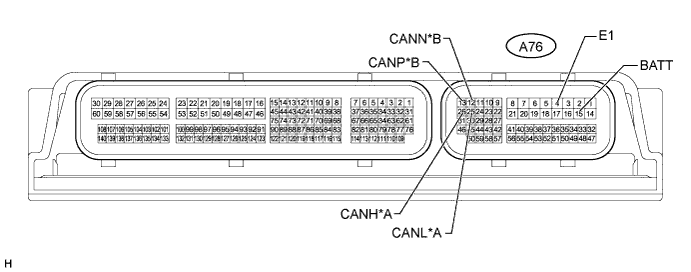
Text in Illustration *A for V1 Bus *B for Power Management Bus
-
Disconnect the A76 ECM connector.
-
Measure the resistance according to the value(s) in the table below.
for V1 Bus Terminal No. (Symbol) Wiring Color Switch Condition Specified Condition A76-26 (CANH) - A76-25 (CANL) Y - W Ignition switch off 108 to 132 Ω A76-26 (CANH) - A76-4 (E1) Y - W-B Ignition switch off 200 Ω or higher A76-25 (CANL) - A76-4 (E1) W - W-B Ignition switch off 200 Ω or higher A76-26 (CANH) - A76-15 (BATT) Y - B Ignition switch off 6 kΩ or higher A76-25 (CANL) - A76-15 (BATT) W - B Ignition switch off 6 kΩ or higher for Power Management Bus Terminal No. (Symbol) Wiring Color Switch Condition Specified Condition A76-13 (CANP) - A76-12 (CANN) R - W Ignition switch off 108 to 132 Ω A76-13 (CANP) - A76-4 (E1) R - W-B Ignition switch off 200 Ω or higher A76-12 (CANN) - A76-4 (E1) W - W-B Ignition switch off 200 Ω or higher A76-13 (CANP) - A76-15 (BATT) R - B Ignition switch off 6 kΩ or higher A76-12 (CANN) - A76-15 (BATT) W - B Ignition switch off 6 kΩ or higher
-
-
CHECK POWER MANAGEMENT CONTROL ECU (w/ Entry and Start System)
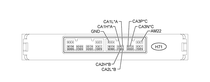
Text in Illustration *A for V1 Bus *B for V2 Bus *C for Power Management Bus - -
-
Disconnect the H71 power management control ECU connector.
-
Measure the resistance according to the value(s) in the table below.
for V1 Bus Terminal No. (Symbol) Wiring Color Switch Condition Specified Condition H71-14 (CA1H) - H71-13 (CA1L) G - W Ignition switch off 54 to 69 Ω H71-14 (CA1H) - H71-6 (GND) G - W-B Ignition switch off 200 Ω or higher H71-13 (CA1L) - H71-6 (GND) W - W-B Ignition switch off 200 Ω or higher H71-14 (CA1H) - H71-1 (AM22) G - L Ignition switch off 6 kΩ or higher H71-13 (CA1L) - H71-1 (AM22) W - L Ignition switch off 6 kΩ or higher for V2 Bus Terminal No. (Symbol) Wiring Color Switch Condition Specified Condition H71-26 (CA2H) - H71-25 (CA2L) B - W Ignition switch off 108 to 132 Ω H71-26 (CA2H) - H71-6 (GND) B - W-B Ignition switch off 200 Ω or higher H71-25 (CA2L) - H71-6 (GND) W - W-B Ignition switch off 200 Ω or higher H71-26 (CA2H) - H71-1 (AM22) B - L Ignition switch off 6 kΩ or higher H71-25 (CA2L) - H71-1 (AM22) W - L Ignition switch off 6 kΩ or higher for Power Management Bus Terminal No. (Symbol) Wiring Color Switch Condition Specified Condition H71-12 (CA3P) - H71-11 (CA3N) G - W Ignition switch off 108 to 132 Ω H71-12 (CA3P) - H71-6 (GND) G - W-B Ignition switch off 200 Ω or higher H71-11 (CA3N) - H71-6 (GND) W - W-B Ignition switch off 200 Ω or higher H71-12 (CA3P) - H71-1 (AM22) G - L Ignition switch off 6 kΩ or higher H71-11 (CA3N) - H71-1 (AM22) W - L Ignition switch off 6 kΩ or higher
-
-
CHECK POWER MANAGEMENT CONTROL ECU (w/o Entry and Start System)

-
Disconnect the H72 power management control ECU connector.
-
Measure the resistance according to the value(s) in the table below.
Terminal No. (Symbol) Wiring Color Switch Condition Specified Condition H72-4 (CA3P) - H72-3 (CA3N) R - W Ignition switch off 108 to 132 Ω H72-4 (CA3P) - H72-12 (GND) R - W-B Ignition switch off 200 Ω or higher H72-3 (CA3N) - H72-12 (GND) W - W-B Ignition switch off 200 Ω or higher H72-4 (CA3P) - H72-8 (AM21) R - B Ignition switch off 6 kΩ or higher H72-3 (CA3N) - H72-8 (AM21) W - B Ignition switch off 6 kΩ or higher
-
-
CHECK MAIN BODY ECU (INSTRUMENT PANEL JUNCTION BLOCK ASSEMBLY)
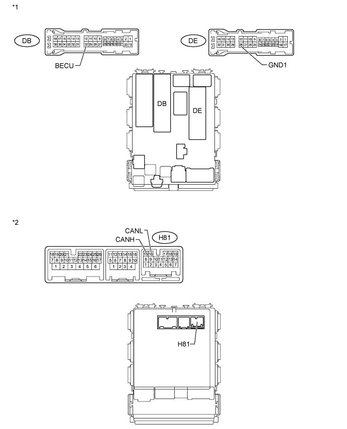
Text in Illustration *1 Vehicle Rear Side *2 Vehicle Front Side
-
Disconnect the H81, DB and DE main body ECU (instrument panel junction block assembly) connectors.
-
Measure the resistance according to the value(s) in the table below.
Terminal No. (Symbol) Wiring Color Switch Condition Specified Condition H81-15 (CANH) - H81-16 (CANL) R - W Ignition switch off 54 to 69 Ω H81-15 (CANH) - DE-28 (GND1) R - W-B Ignition switch off 200 Ω or higher H81-16 (CANL) - DE-28 (GND1) W - W-B Ignition switch off 200 Ω or higher H81-15 (CANH) - DB-30 (BECU) R - W Ignition switch off 6 kΩ or higher H81-16 (CANL) - DB-30 (BECU) W - W Ignition switch off 6 kΩ or higher
-
-
CHECK BRAKE ACTUATOR ASSEMBLY (SKID CONTROL ECU)
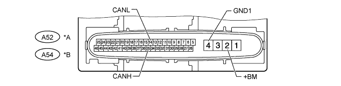
Text in Illustration *A for 1AD-FTV, 2AD-FHV, 1WW *B for 1ZR-FAE, 2ZR-FAE
-
Disconnect the A52*1 or A54*2 brake actuator assembly (skid control ECU) connector.
-
*1: for 1AD-FTV, 2AD-FHV, 1WW
-
*2: for 1ZR-FAE, 2ZR-FAE
-
-
Measure the resistance according to the value(s) in the table below.
for 1AD-FTV, 2AD-FHV, 1WW Terminal No. (Symbol) Wiring Color Switch Condition Specified Condition A52-35 (CANH) - A52-14 (CANL) R - W Ignition switch off 54 to 69 Ω A52-35 (CANH) - A52-4 (GND1) R - W-B Ignition switch off 200 Ω or higher A52-14 (CANL) - A52-4 (GND1) W - W-B Ignition switch off 200 Ω or higher A52-35 (CANH) - A52-2 (+BM) R - L Ignition switch off 6 kΩ or higher A52-14 (CANL) - A52-2 (+BM) W - L Ignition switch off 6 kΩ or higher for 1ZR-FAE, 2ZR-FAE Terminal No. (Symbol) Wiring Color Switch Condition Specified Condition A54-35 (CANH) - A54-14 (CANL) R - W Ignition switch off 54 to 69 Ω A54-35 (CANH) - A54-4 (GND1) R - W-B Ignition switch off 200 Ω or higher A54-14 (CANL) - A54-4 (GND1) W - W-B Ignition switch off 200 Ω or higher A54-35 (CANH) - A54-2 (+BM) R - L Ignition switch off 6 kΩ or higher A54-14 (CANL) - A54-2 (+BM) W - L Ignition switch off 6 kΩ or higher
-
-
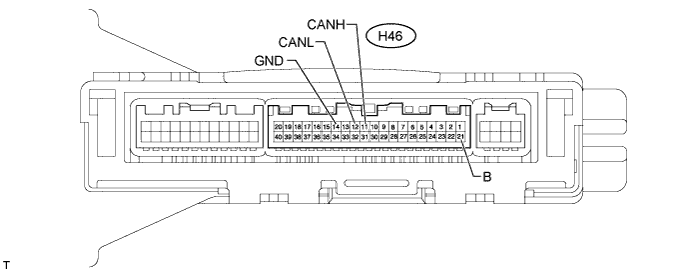
CHECK AIR CONDITIONING AMPLIFIER ASSEMBLY (for Automatic Air Conditioning System)
-
Disconnect the H46 air conditioning amplifier assembly connector.
-
Measure the resistance according to the value(s) in the table below.
Terminal No. (Symbol) Wiring Color Condition Specified Condition H46-11 (CANH) - H46-12 (CANL) V - W Ignition switch off 54 to 69 Ω H46-11 (CANH) - H46-14 (GND) V - W-B Ignition switch off 200 Ω or higher H46-12 (CANL) - H46-14 (GND) W - W-B Ignition switch off 200 Ω or higher H46-11 (CANH) - H46-21 (B) V - W Ignition switch off 6 kΩ or higher H46-12 (CANL) - H46-21 (B) W - W Ignition switch off 6 kΩ or higher
-
-
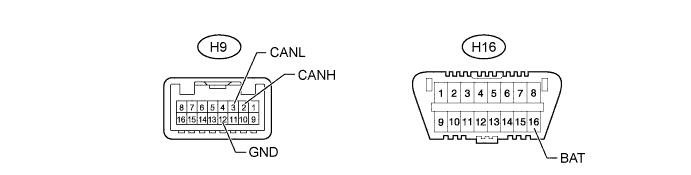
CHECK AIR CONDITIONING AMPLIFIER ASSEMBLY (for Manual Air Conditioning System or w/o Air Conditioning System)
-
except 1WW:
-
Disconnect the H9 air conditioning amplifier assembly connector.
-
Measure the resistance according to the value(s) in the table below.
Terminal No. (Symbol) Wiring Color Condition Specified Condition H9-2 (CANH) - H9-3 (CANL) V - W Ignition switch off 54 to 69 Ω H9-2 (CANH) - H9-12 (GND) V - W-B Ignition switch off 200 Ω or higher H9-3 (CANL) - H9-12 (GND) W - W-B Ignition switch off 200 Ω or higher H9-2 (CANH) - H16-16 (BAT) V - G Ignition switch off 6 kΩ or higher H9-3 (CANL) - H16-16 (BAT) W - G Ignition switch off 6 kΩ or higher
-
-
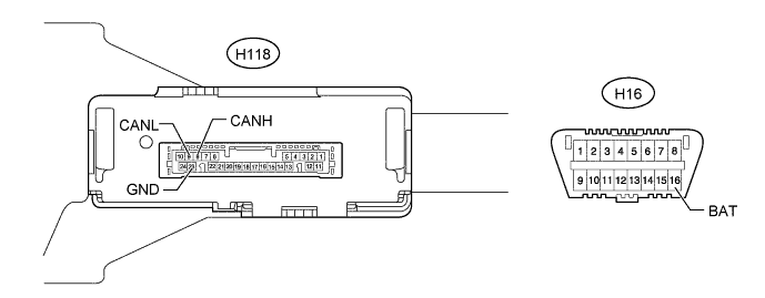
for 1WW:
-
Disconnect the H118 air conditioning amplifier assembly connector.
-
Measure the resistance according to the value(s) in the table below.
Terminal No. (Symbol) Wiring Color Condition Specified Condition H118-8 (CANH) - H118-9 (CANL) V - W Ignition switch off 54 to 69 Ω H118-8 (CANH) - H118-23 (GND) V - W-B Ignition switch off 200 Ω or higher H118-9 (CANL) - H118-23 (GND) W - W-B Ignition switch off 200 Ω or higher H118-8 (CANH) - H16-16 (BAT) V - G Ignition switch off 6 kΩ or higher H118-9 (CANL) - H16-16 (BAT) W - G Ignition switch off 6 kΩ or higher
-
-
-
CHECK COMBINATION METER ASSEMBLY

-
Disconnect the H62 combination meter assembly connector.
-
Measure the resistance according to the value(s) in the table below.
Terminal No. (Symbol) Wiring Color Switch Condition Specified Condition H62-22 (CANH) - H62-23 (CANL) SB - W Ignition switch off 108 to 132 Ω H62-22 (CANH) - H62-21 (ET) SB - BR Ignition switch off 200 Ω or higher H62-23 (CANL) - H62-21 (ET) W - BR Ignition switch off 200 Ω or higher H62-22 (CANH) - H62-40 (B) SB - W Ignition switch off 6 kΩ or higher H62-23 (CANL) - H62-40 (B) W - W Ignition switch off 6 kΩ or higher
-
-
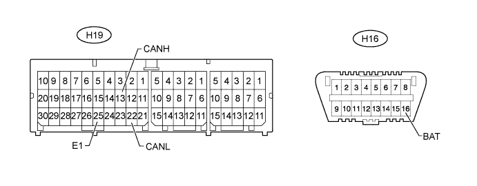
CHECK CENTER AIRBAG SENSOR ASSEMBLY
-
Disconnect the H19 center airbag sensor assembly connector Click here.
-
Measure the resistance according to the value(s) in the table below.
Terminal No. (Symbol) Wiring Color Switch Condition Specified Condition H19-13 (CANH) - H19-22 (CANL) Y - W Ignition switch off 54 to 69 Ω H19-13 (CANH) - H19-25 (E1) Y - W-B Ignition switch off 200 Ω or higher H19-22 (CANL) - H19-25 (E1) W - W-B Ignition switch off 200 Ω or higher H19-13 (CANH) - H16-16 (BAT) Y - G Ignition switch off 6 kΩ or higher H19-22 (CANL) - H16-16 (BAT) W - G Ignition switch off 6 kΩ or higher
-
-
CHECK SPIRAL WITH SENSOR CABLE SUB-ASSEMBLY (STEERING ANGLE SENSOR)
-
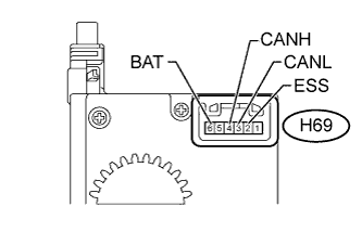
Disconnect the H69 spiral with sensor cable sub-assembly (steering angle sensor) connector.
-
Measure the resistance according to the value(s) in the table below.
Terminal No. (Symbol) Wiring Color Switch Condition Specified Condition H69-4 (CANH) - H69-3 (CANL) BR - W Ignition switch off 54 to 69 Ω H69-4 (CANH) - H69-2 (ESS) BR - BR Ignition switch off 200 Ω or higher H69-3 (CANL) - H69-2 (ESS) W - BR Ignition switch off 200 Ω or higher H69-4 (CANH) - H69-6 (BAT) BR - W Ignition switch off 6 kΩ or higher H69-3 (CANL) - H69-6 (BAT) W - W Ignition switch off 6 kΩ or higher
-
-
CHECK YAW RATE SENSOR
-
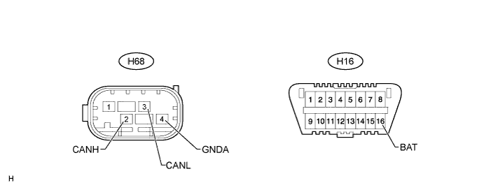
Disconnect the H68 yaw rate sensor connector.
-
Measure the resistance according to the value(s) in the table below.
Terminal No. (Symbol) Wiring Color Switch Condition Specified Condition H68-2 (CANH) - H68-3 (CANL) L - W Ignition switch off 54 to 69 Ω H68-2 (CANH) - H68-4 (GNDA) L - BR Ignition switch off 200 Ω or higher H68-3 (CANL) - H68-4 (GNDA) W - BR Ignition switch off 200 Ω or higher H68-2 (CANH) - H16-16 (BAT) L - G Ignition switch off 6 kΩ or higher H68-3 (CANL) - H16-16 (BAT) W - G Ignition switch off 6 kΩ or higher
-
-
CHECK POWER STEERING ECU ASSEMBLY
-
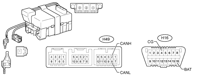
Disconnect the H49 power steering ECU assembly connector.
-
Measure the resistance according to the value(s) in the table below.
Terminal No. (Symbol) Wiring Color Switch Condition Specified Condition H49-2 (CANH) - H49-8 (CANL) SB - W Ignition switch off 54 to 69 Ω H49-2 (CANH) - H16-4 (CG) SB - W-B Ignition switch off 200 Ω or higher H49-8 (CANL) - H16-4 (CG) W - W-B Ignition switch off 200 Ω or higher H49-2 (CANH) - H16-16 (BAT) SB - G Ignition switch off 6 kΩ or higher H49-8 (CANL) - H16-16 (BAT) W - G Ignition switch off 6 kΩ or higher
-
-
CHECK CERTIFICATION ECU (SMART KEY ECU ASSEMBLY) (w/ Entry and Start System)
-
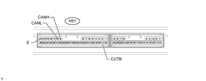
Disconnect the H51 certification ECU (smart key ECU assembly) connector.
-
Measure the resistance according to the value(s) in the table below.
Terminal No. (Symbol) Wiring Color Switch Condition Specified Condition H51-9 (CANH) - H51-10 (CANL) SB - W Ignition switch off 54 to 69 Ω H51-9 (CANH) - H51-15 (E) SB - W-B Ignition switch off 200 Ω or higher H51-10 (CANL) - H51-15 (E) W - W-B Ignition switch off 200 Ω or higher H51-9 (CANH) - H51-17 (CUTB) SB - W Ignition switch off 6 kΩ or higher H51-10 (CANL) - H51-17 (CUTB) W - W Ignition switch off 6 kΩ or higher
-
-
CHECK RADIO AND DISPLAY RECEIVER ASSEMBLY (for Radio and Display Type)
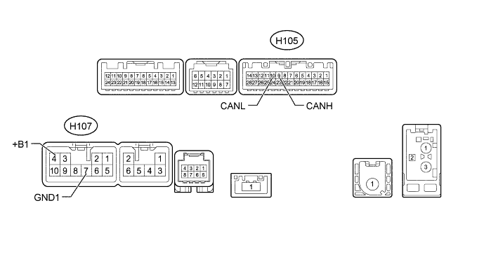
-
Disconnect the H105 and H107 radio and display receiver assembly connectors.
-
Measure the resistance according to the value(s) in the table below.
Terminal No. (Symbol) Wiring Color Switch Condition Specified Condition H105-9 (CANH) - H105-10 (CANL) SB - W Ignition switch off 54 to 69 Ω H105-9 (CANH) - H107-7 (GND1) SB - BR Ignition switch off 200 Ω or higher H105-10 (CANL) - H107-7 (GND1) W - BR Ignition switch off 200 Ω or higher H105-9 (CANH) - H107-4 (+B1) SB - SB Ignition switch off 6 kΩ or higher H105-10 (CANL) - H107-4 (+B1) W - SB Ignition switch off 6 kΩ or higher
-
-
CHECK ENGINE STOP AND START ECU (w/ Stop and Start System)
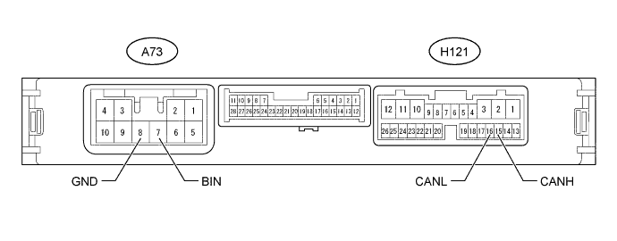
-
Disconnect the A73 and H121 engine stop and start ECU connectors.
-
Measure the resistance according to the value(s) in the table below.
Terminal No. (Symbol) Wiring Color Switch Condition Specified Condition H121-15 (CANH) - H121-16 (CANL) P - W Ignition switch off 54 to 69 Ω H121-15 (CANH) - A73-8 (GND) P - W-B Ignition switch off 200 Ω or higher H121-16 (CANL) - A73-8 (GND) W - W-B Ignition switch off 200 Ω or higher H121-15 (CANH) - A73-7 (BIN) P - L Ignition switch off 6 kΩ or higher H121-16 (CANL) - A73-7 (BIN) W - L Ignition switch off 6 kΩ or higher
-
-
CHECK DRIVING SUPPORT ECU ASSEMBLY (for 1WW [w/ Cruise Control System])
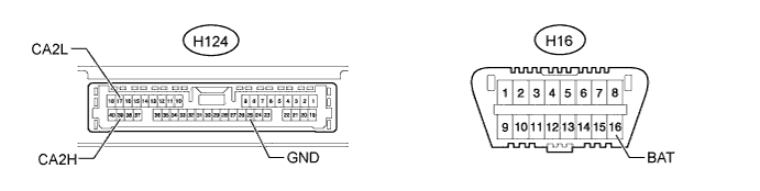
-
Disconnect the H124 driving support ECU assembly connector.
-
Measure the resistance according to the value(s) in the table below.
Terminal No. (Symbol) Wiring Color Switch Condition Specified Condition H124-39 (CA2H) - H124-17 (CA2L) L - W*1
SB - W*2
Ignition switch off 54 to 69 Ω H124-39 (CA2H) - H124-25 (GND) L - R*1
SB - R*2
Ignition switch off 200 Ω or higher H124-17 (CA2L) - H124-25 (GND) W - R Ignition switch off 200 Ω or higher H124-39 (CA2H) - H16-16 (BAT) L - G*1
SB - G*2
Ignition switch off 6 kΩ or higher H124-17 (CA2L) - H16-16 (BAT) W - G Ignition switch off 6 kΩ or higher
-
*1: w/ Entry and Start System
-
*2: w/o Entry and Start System
-
-
-
CHECK TRANSMISSION CONTROL ECU ASSEMBLY (for Automatic Transaxle System)
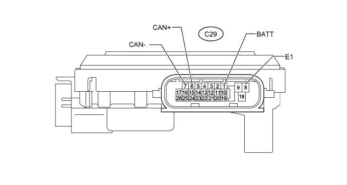
-
Disconnect the C29 transmission control ECU assembly connector.
-
Measure the resistance according to the value(s) in the table below.
Terminal No. (Symbol) Wiring Color Switch Condition Specified Condition C29-6 (CAN+) - C29-7 (CAN-) L - W Ignition switch off 54 to 69 Ω C29-6 (CAN+) - C29-8 (E1) L - BR Ignition switch off 200 Ω or higher C29-7 (CAN-) - C29-8 (E1) W - BR Ignition switch off 200 Ω or higher C29-6 (CAN+) - C29-1 (BATT) L - W Ignition switch off 6 kΩ or higher C29-7 (CAN-) - C29-1 (BATT) W - W Ignition switch off 6 kΩ or higher
-
-
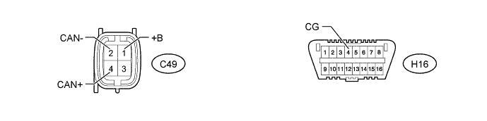
CHECK CONTINUOUSLY VARIABLE VALVE LIFT CONTROLLER ASSEMBLY (for 1ZR-FAE, 2ZR-FAE)
-
Disconnect the C49 continuously variable valve lift controller assembly connector. .
-
Measure the resistance according to the value(s) in the table below.
Terminal No. (Symbol) Wiring Color Switch Condition Specified Condition C49-4 (CAN+) - C49-2 (CAN-) Y - W Ignition switch off 54 to 69 Ω C49-4 (CAN+) - H16-4 (CG) Y - W-B Ignition switch off 200 Ω or higher C49-2 (CAN-) - H16-4 (CG) W - W-B Ignition switch off 200 Ω or higher C49-4 (CAN+) - C49-1 (+B) Y - B Ignition switch off 6 kΩ or higher C49-2 (CAN-) - C49-1 (+B) W - B Ignition switch off 6 kΩ or higher
-