LIN COMMUNICATION SYSTEM Rain Sensor LIN Communication Malfunction
DESCRIPTION
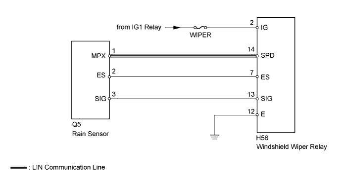
The LIN communication of the components related to the rain sensor occurs between the rain sensor and windshield wiper relay.
WIRING DIAGRAM
INSPECTION PROCEDURE
Note
-
When using the intelligent tester with the ignition switch off to troubleshoot:
Connect the intelligent tester to the vehicle, and turn a courtesy light switch on and off at 1.5 second intervals until communication between the intelligent tester and vehicle begins.
-
Inspect the fuses and bulbs for circuits related to this system before performing the following inspection procedure.
PROCEDURE
-
CHECK HARNESS AND CONNECTOR (RAIN SENSOR - WINDSHIELD WIPER RELAY)
-
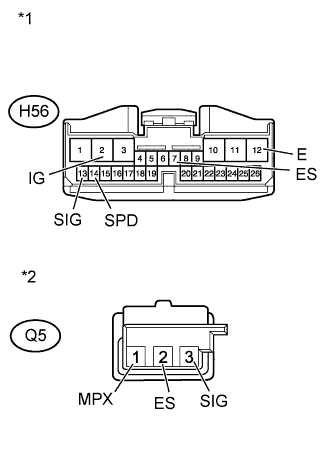
Text in Illustration *1 Front view of wire harness connector
(to Windshield Wiper Relay)
*2 Front view of wire harness connector
(to Rain Sensor)
Disconnect the H56 relay connector.
-
Disconnect the Q5 sensor connector.
-
Measure the resistance and voltage according to the value(s) in the table below.
Standard Resistance Tester Connection Condition Specified Condition Q5-1 (MPX) - H56-14 (SPD) Always Below 1 Ω Q5-3 (SIG) - H56-13 (SIG) Always Below 1 Ω Q5-2 (ES) - H56-7 (ES) Always Below 1 Ω Q5-1 (MPX) - Body ground Always 10 kΩ or higher Q5-3 (SIG) - Body ground Always 10 kΩ or higher Q5-2 (ES) - Body ground Always 10 kΩ or higher H56-12 (E) - Body ground Always Below 1 Ω Standard Voltage Tester Connection Switch Condition Specified Condition H56-2 (IG) - Body ground Ignition switch ON 11 to 14 V
NG 
REPAIR OR REPLACE HARNESS OR CONNECTOR
OK 
-
-
CHECK WINDSHIELD WIPER RELAY ASSEMBLY
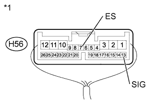
Text in Illustration *1 Component with harness connected
(Windshield Wiper Relay)
-
Connect the H56 relay connector.
-
Measure the voltage according to the value(s) in the table below.
Standard Voltage Tester Connection Switch Condition Specified Condition H56-13 (SIG) - H56-7 (ES) Ignition switch ON 11 to 14 V Result Result Proceed to OK A NG (for LHD) B NG (for RHD) C
B
REPLACE WINDSHIELD WIPER RELAY ASSEMBLY Click here
C
REPLACE WINDSHIELD WIPER RELAY ASSEMBLY Click here
A
-
-
REPLACE RAIN SENSOR
-
Temporarily replace the rain sensor with a new one Click here.
-
Check that the rain sensor function is normal.
OK Rain sensor function is normal. Result Result Proceed to OK A NG (for LHD) B NG (for RHD) C
B
REPLACE WINDSHIELD WIPER RELAY ASSEMBLY Click here
C
REPLACE WINDSHIELD WIPER RELAY ASSEMBLY Click here
A 
END (RAIN SENSOR IS DEFECTIVE)
-