CAN COMMUNICATION SYSTEM SYSTEM DIAGRAM

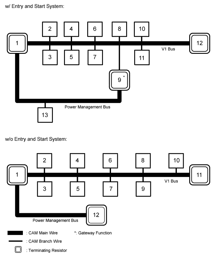
| No. | ECU/Sensor Name |
|---|---|
| 1 | ECM |
| 2 | Brake actuator assembly (VSC ECU) |
| 3 | Certification ECU |
| 4 | Power steering ECU assembly |
| 5 | Spiral cable sub-assembly (steering angle sensor) |
| 6 | Yaw rate sensor |
| 7 | Main body ECU (instrument panel junction block assembly) |
| 8 | DLC3 |
| 9 | Power management control ECU |
| 10 | Center airbag sensor assembly |
| 11 | Radio and display receiver assembly* |
| 12 | Combination meter assembly |
| 13 | Air conditioning amplifier assembly |
-
*: for Radio and Display Type
| No. | ECU/Sensor Name |
|---|---|
| 1 | ECM |
| 2 | Brake actuator assembly (VSC ECU) |
| 3 | Power steering ECU assembly |
| 4 | Air conditioning amplifier assembly |
| 5 | Spiral cable sub-assembly (steering angle sensor) |
| 6 | Yaw rate sensor |
| 7 | DLC3 |
| 8 | Main body ECU (instrument panel junction block assembly) |
| 9 | Center airbag sensor assembly |
| 10 | Radio and display receiver assembly* |
| 11 | Combination meter assembly |
| 12 | Power management control ECU |
-
*: for Radio and Display Type
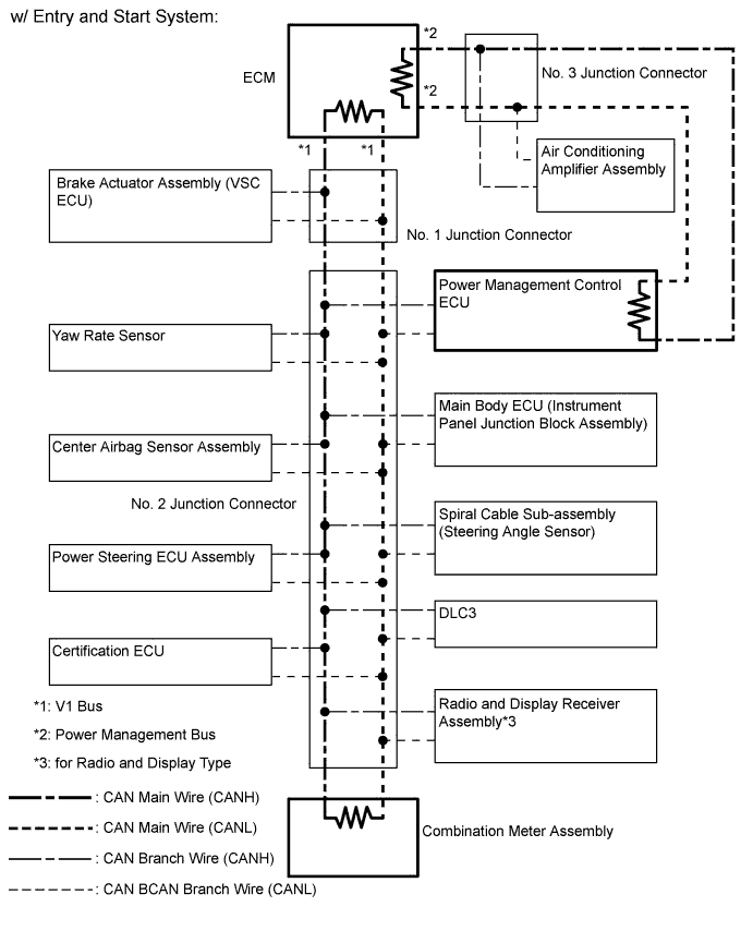
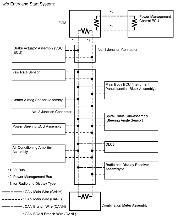
Tech Tips
-
The brake actuator assembly (VSC ECU) stores spiral cable sub-assembly (steering angle sensor) and yaw rate sensor DTCs and performs DTC communication by receiving information from the spiral cable sub-assembly (steering angle sensor) and yaw rate sensor.
-
The ECM uses the CAN communication system to perform DTC communication instead of the conventional communication line (SIL).