POWER MANAGEMENT CONTROL ECU (for RHD) INSTALLATION

Tech Tips
A bolt without a torque specification is shown in the standard bolt chart Click here.
-
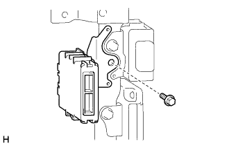
INSTALL POWER MANAGEMENT CONTROL ECU (for Type A)
-
Install the power management control ECU with the bolt.
- Torque:
- 13 N*m { 127 kgf*cm, 9 ft.*lbf }
-
Connect each connector.
-
Install the fuse box opening cover Click here.
-
Install the No. 2 switch hole base Click here.
-
Install the instrument panel finish panel end RH Click here.
-
-
INSTALL POWER MANAGEMENT CONTROL ECU (for Type B, for Type C)
-
Install the power management control ECU with the 3 bolts.
- Torque:
- for Bolt A
- 13 N*m { 127 kgf*cm, 9 ft.*lbf }
-
Connect each connector.
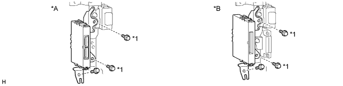
Text in Illustration *A for Type B *B for Type C *1 Bolt A - - -
Install the lower instrument panel sub-assembly Click here.
-
Install the instrument panel safety pad sub-assembly Click here.
-
-
CONNECT CABLE TO NEGATIVE BATTERY TERMINAL
Note
When disconnecting the cable, some systems need to be initialized after the cable is reconnected Click here.