POWER MANAGEMENT CONTROL ECU (for LHD) INSTALLATION

Tech Tips
A bolt without a torque specification is shown in the standard bolt chart Click here.
-
INSTALL POWER MANAGEMENT CONTROL ECU (for Type A)
-
Install the power management control ECU with the screw.
-
Connect each connector.
-
Install the glove compartment door assembly Click here.
-
Install the glove compartment door sub-assembly Click here.
-
-
INSTALL POWER MANAGEMENT CONTROL ECU (for Type B, for Type C, for Type D)
-
Attach the 2 claws to install the power management control ECU to the ECU integration box RH.
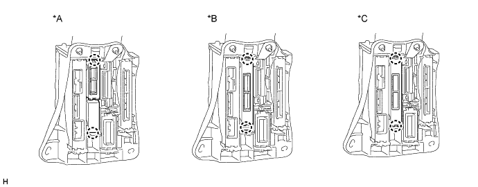
Text in Illustration *A for Type B *B for Type C *C for Type D - - -
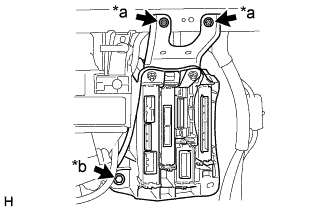
Text in Illustration *a Screw *b Bolt Install the ECU integration box RH with the 2 screws and bolt.
-
Connect each connector.
-
Install the lower instrument panel sub-assembly Click here.
-
Install the instrument panel safety pad sub-assembly Click here.
-
-
CONNECT CABLE TO NEGATIVE BATTERY TERMINAL
Note
When disconnecting the cable, some systems need to be initialized after the cable is reconnected Click here.