CHARGING SYSTEM, Diagnostic DTC:P1602

| DTC Code | DTC Name |
|---|---|
| P1602 | Deterioration of Battery |
DESCRIPTION
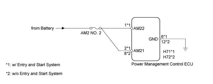
The power management control ECU monitors the battery. When the engine is running (not cranking) and the battery voltage drops below a specified level, the ECU determines that there is battery deterioration and stores this DTC.
| DTC Code | DTC Detection Condition | Trouble Area |
|---|---|---|
| P1602 | When the engine is running (not cranking) and all the electrical systems are turned off, the battery voltage is below 11.85 V for 10 seconds or more (1 trip detection logic). |
|
WIRING DIAGRAM
INSPECTION PROCEDURE
PROCEDURE
-
CHECK FOR DTC
-
Connect the intelligent tester to the DLC3.
-
Turn the ignition switch to ON.
-
Turn the tester on.
-
According to the display on the tester, check for DTCs Click here.
Result Result Proceed to Only DTC P1602 is output. A Other DTCs are output in addition to DTC P1602. B
B 
GO TO DIAGNOSTIC TROUBLE CODE CHART Click here
A 
-
-
CHECK CHARGING SYSTEM
-
Check the charging system Click here.
Result Result Proceed to OK w/ Entry and Start System A w/o Entry and Start System B NG C
B 
CHECK HARNESS AND CONNECTOR (POWER SOURCE CIRCUIT) Click here
C
REPAIR OR REPLACE CHARGING SYSTEM
A
-
-
CHECK HARNESS AND CONNECTOR (POWER SOURCE CIRCUIT)
-
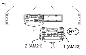
Text in Illustration *1 Rear view of wire harness connector
(to Power Management Control ECU)
Disconnect the H71 power management control ECU connector.
-
Measure the voltage according to the value(s) in the table below.
Standard Voltage Tester Connection Condition Specified Condition H71-2 (AM21) - Body ground Always 9.5 to 16 V H71-1 (AM22) - Body ground
NG
CHECK HARNESS AND CONNECTOR (GROUND CIRCUIT) Click here
OK 
USE SIMULATION METHOD TO CHECK Click here
-
-
CHECK HARNESS AND CONNECTOR (POWER SOURCE CIRCUIT)
-
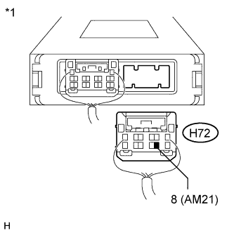
Text in Illustration *1 Rear view of wire harness connector
(to Power Management Control ECU)
Disconnect the H72 power management control ECU connector.
-
Measure the voltage according to the value(s) in the table below.
Standard Voltage Tester Connection Condition Specified Condition H72-8 (AM21) - Body ground Always 9.5 to 16 V
NG
CHECK HARNESS AND CONNECTOR (GROUND CIRCUIT) Click here
OK
USE SIMULATION METHOD TO CHECK Click here
-
-
CHECK HARNESS AND CONNECTOR (GROUND CIRCUIT)
-
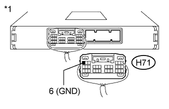
Text in Illustration *1 Rear view of wire harness connector
(to Power Management Control ECU)
Measure the resistance according to the value(s) in the table below.
Standard Resistance Tester Connection Condition Specified Condition H71-6 (GND) - Body ground Always Below 1 Ω
NG
REPAIR OR REPLACE HARNESS OR CONNECTOR (GROUND CIRCUIT)
OK
REPAIR OR REPLACE HARNESS OR CONNECTOR (POWER SOURCE CIRCUIT)
-
-
CHECK HARNESS AND CONNECTOR (GROUND CIRCUIT)
-
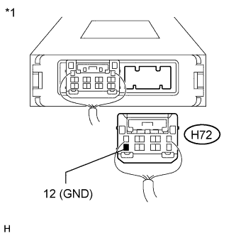
Text in Illustration *1 Rear view of wire harness connector
(to Power Management Control ECU)
Measure the resistance according to the value(s) in the table below.
Standard Resistance Tester Connection Condition Specified Condition H72-12 (GND) - Body ground Always Below 1 Ω
NG
REPAIR OR REPLACE HARNESS OR CONNECTOR (GROUND CIRCUIT)
OK
REPAIR OR REPLACE HARNESS OR CONNECTOR (POWER SOURCE CIRCUIT)
-