CLEARANCE WARNING ECU REMOVAL

Tech Tips
-
Use the same procedure for RHD and LHD vehicles.
-
The procedure listed below is for LHD vehicles.
-
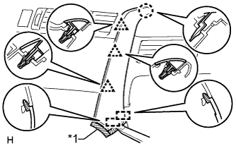
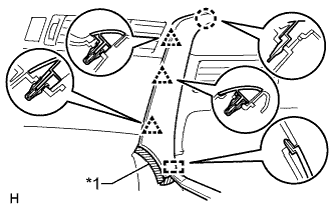
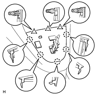
REMOVE INSTRUMENT PANEL FINISH PANEL END LH
-
for Automatic Air Conditioning System:
-
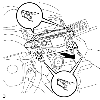
Text in Illustration *1 Protective Tape Put protective tape around the instrument panel finish panel end LH.
-
Using a moulding remover A, detach the 3 clips and 2 guides, and remove the instrument panel finish panel end LH.
-
-
for Manual Air Conditioning System:
-
Text in Illustration *1 Protective Tape Put protective tape around the instrument panel finish panel end LH.
-
Using a moulding remover A, detach the 3 clips and guide, and remove the instrument panel finish panel end LH.
-
-
-
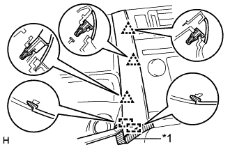
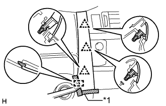
REMOVE INSTRUMENT PANEL FINISH PANEL END RH
Text in Illustration *1 Protective Tape
-
for Automatic Air Conditioning System:
-
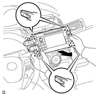
Put protective tape around the instrument panel finish panel end RH.
-
Using a moulding remover A, detach the 3 clips, claw and 2 guides, and remove the instrument panel finish panel end RH.
-
-
Text in Illustration *1 Protective Tape for Manual Air Conditioning System:
-
Put protective tape around the instrument panel finish panel end RH.
-
Using a moulding remover A, detach the 3 clips, claw and guide, and remove the instrument panel finish panel end.
-
-
-
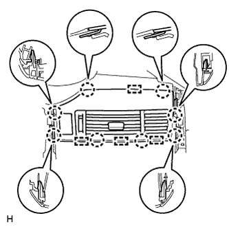
REMOVE CENTER INSTRUMENT PANEL REGISTER ASSEMBLY
-
Detach the 8 claws and 4 guides.
-
Disconnect the connector and remove the center instrument panel register.
-
-
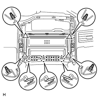
REMOVE CENTER INSTRUMENT CLUSTER FINISH PANEL SUB-ASSEMBLY (w/o Audio)
-
Detach the 4 clips, 3 claws and 3 guides, and remove the center instrument cluster finish panel.
-
-
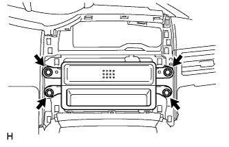
REMOVE STEREO OPENING COVER WITH BRACKET (w/o Audio)
-
Remove the 4 bolts and stereo opening cover.
-
-
REMOVE RADIO RECEIVER ASSEMBLY WITH BRACKET (w/ Audio, for Radio Receiver Type)
-
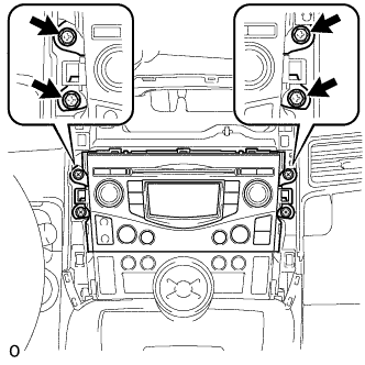
Remove the 4 screws.
-
Pull the radio receiver assembly with bracket to detach the 4 clips on the backside of the radio receiver assembly with bracket.
-
Disconnect the connectors and remove the radio receiver assembly with bracket.
-
-
REMOVE RADIO AND DISPLAY RECEIVER ASSEMBLY WITH BRACKET (w/ Audio, for Radio Receiver Type)
-
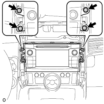
Remove the 4 screws.
-
Pull the radio receiver and display receiver assembly with bracket to detach the 4 clips on the backside of the radio and display receiver assembly with bracket.
-
Disconnect the connectors and remove the radio and display receiver assembly with bracket.
-
-
REMOVE SHIFT LEVER KNOB SUB-ASSEMBLY
-
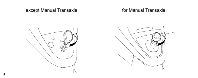
Twist the shift lever knob in the direction indicated by the arrow and remove it.
-
-
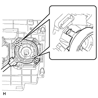
REMOVE POSITION INDICATOR HOUSING ASSEMBLY (except Manual Transaxle)
-
Detach the 5 claws and 3 clips.
-
Disconnect the connector and remove the position indicator housing.
-
-
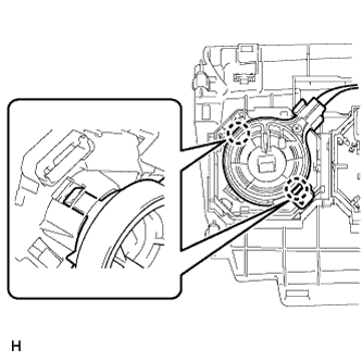
REMOVE SHIFTING HOLE COVER (for Manual Transaxle)
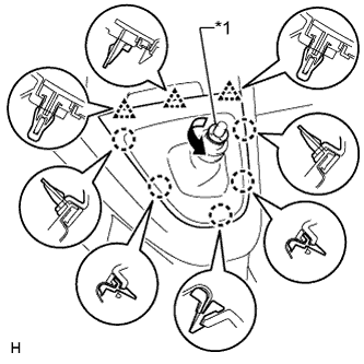
Text in Illustration *1 T Washer
-
Twist the T washer in the direction indicated by the arrow and remove it.
-
Remove the knob spring.
-
Detach the 5 claws and 3 clips, and remove the shifting hole cover.
-
-
REMOVE LOWER CENTER INSTRUMENT PANEL FINISH PANEL
-
except Manual Transaxle:
-
for Manual Transaxle:
-
-
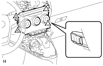
REMOVE AIR CONDITIONING CONTROL ASSEMBLY (for Automatic Air Conditioning System)
-
Detach the 4 clips.
-
Disconnect the connector and remove the air conditioning control.
-
-
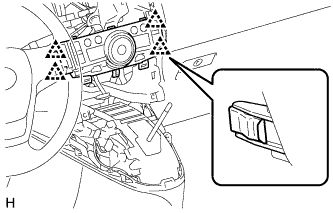
REMOVE CENTER INSTRUMENT CLUSTER FINISH PANEL ASSEMBLY (for Manual Air Conditioning System)
-
Detach the 4 clips and remove the center instrument cluster finish panel assembly.
-
Disconnect each connector.
-
Detach the 2 claws and disconnect the No. 2 heater control cable sub-assembly.
-
Detach the 2 claws and disconnect the air mix damper control cable sub-assembly.
-
-
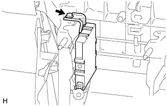
REMOVE CLEARANCE WARNING ECU ASSEMBLY
-
Remove the bolt.
-
Disconnect the connector and remove the clearance warning ECU.
-