TOYOTA PARKING ASSIST-SENSOR SYSTEM Parking Brake Switch Circuit
DESCRIPTION
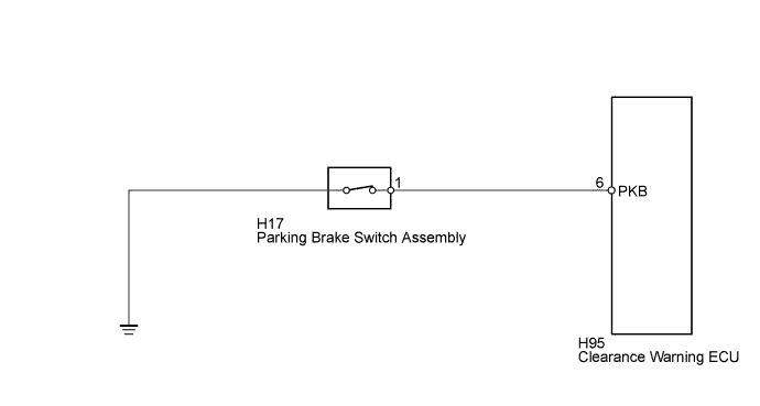
This circuit includes the parking brake switch and the clearance warning ECU.
WIRING DIAGRAM
INSPECTION PROCEDURE
PROCEDURE
-
CHECK HARNESS AND CONNECTOR (CLEARANCE WARNING ECU - PARKING BRAKE SWITCH)
-
Disconnect the H95 clearance warning ECU connector.
-
Disconnect the H17 parking brake switch assembly connector.
-
Measure the resistance according to the value(s) in the table below.
Standard Resistance Tester Connection Condition Specified Condition H95-6 (PKB) - H17-1 Always Below 1 Ω H95-6 (PKB) - Body ground Always 10 kΩ or higher
NG 
REPAIR OR REPLACE HARNESS OR CONNECTOR
OK 
-
-
INSPECT PARKING BRAKE SWITCH ASSEMBLY
-
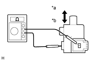
Text in Illustration *a ON *b OFF Remove the parking brake switch assembly Click here.
-
Measure the resistance according to the value(s) in the table below.
Standard Resistance Tester Connection Switch Condition Specified Condition Switch connector terminal - Switch body ON (Shaft not pressed) Below 1 Ω OFF (Shaft pressed) 10 kΩ or higher
NG
REPLACE PARKING BRAKE SWITCH ASSEMBLY Click here
OK 
PROCEED TO NEXT SUSPECTED AREA SHOWN IN PROBLEM SYMPTOMS TABLE Click here
-