TOYOTA PARKING ASSIST-SENSOR SYSTEM Back-up Light Circuit
DESCRIPTION
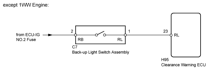
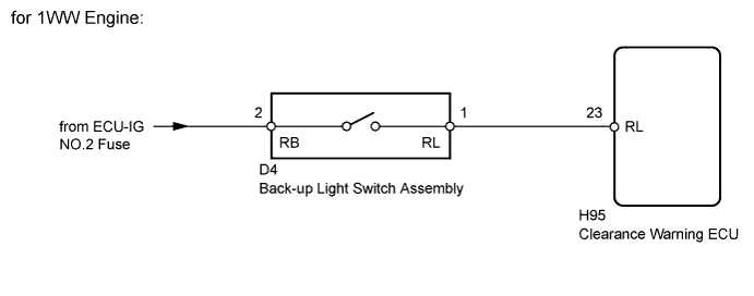
This circuit sends the back-up light switch assembly signals to the clearance warning ECU.
WIRING DIAGRAM
INSPECTION PROCEDURE
Note
Inspect the fuses for circuits related to this system before performing the following inspection procedure.
PROCEDURE
-
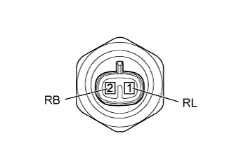
INSPECT BACK-UP LIGHT SWITCH ASSEMBLY
-
Remove the back-up light switch assembly.
-
for EC61: Click here
-
for EC62: Click here
-
for EA62: Click here
-
for EA65: Click here
-
-
Measure the resistance according to the value(s) in the table below.
Standard Resistance Tester Connection Switch Condition Specified Condition 1 (RL) - 2 (RB) Pushed Below 1 Ω 1 (RL) - 2 (RB) Released 10 kΩ or higher Result Result Proceed to OK (except 1WW Engine) A OK (for 1WW Engine) B NG C
-
*: Replacement procedure:
-
for EC61: Click here
-
for EC62: Click here
-
for EA62: Click here
-
for EA65: Click here
-
B 
CHECK HARNESS AND CONNECTOR (BACK-UP LIGHT SWITCH - BATTERY) Click here
C 
REPLACE BACK-UP LIGHT SWITCH ASSEMBLY*
A 
-
-
CHECK HARNESS AND CONNECTOR (BACK-UP LIGHT SWITCH - BATTERY)
-
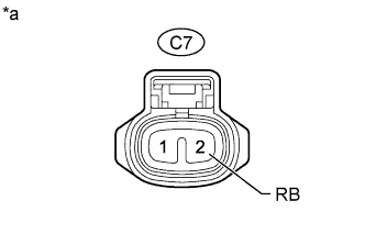
Text in Illustration *a Front view of wire harness connector
(to Back-up Light Switch Assembly)
Disconnect the C7 back-up light switch assembly connector.
-
Measure the voltage according to the value(s) in the table below.
Standard Voltage Tester Connection Switch Condition Specified Condition C7-2 (RB) - Body ground Ignition switch ON 11 to 14 V C7-2 (RB) - Body ground Ignition switch off Below 1 V
NG
REPAIR OR REPLACE HARNESS OR CONNECTOR
OK
-
-
CHECK HARNESS AND CONNECTOR (CLEARANCE WARNING ECU - BACK-UP LIGHT SWITCH)
-
Disconnect the H95 clearance warning ECU connector.
-
Disconnect the C7 back-up light switch assembly connector.
-
Measure the resistance according to the value(s) in the table below.
Standard Resistance Tester Connection Condition Specified Condition H95-23 (RL) - C7-1 (RL) Always Below 1 Ω H95-23 (RL) - Body ground Always 10 kΩ or higher
NG
REPAIR OR REPLACE HARNESS OR CONNECTOR
OK 
PROCEED TO NEXT SUSPECTED AREA SHOWN IN PROBLEM SYMPTOMS TABLE Click here
-
-
CHECK HARNESS AND CONNECTOR (BACK-UP LIGHT SWITCH - BATTERY)
-
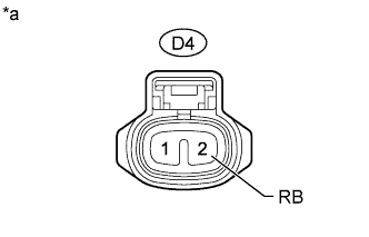
Text in Illustration *a Front view of wire harness connector
(to Back-up Light Switch Assembly)
Disconnect the D4 back-up light switch assembly connector.
-
Measure the voltage according to the value(s) in the table below.
Standard Voltage Tester Connection Switch Condition Specified Condition D4-2 (RB) - Body ground Ignition switch ON 11 to 14 V D4-2 (RB) - Body ground Ignition switch off Below 1 V
NG
REPAIR OR REPLACE HARNESS OR CONNECTOR
OK
-
-
CHECK HARNESS AND CONNECTOR (CLEARANCE WARNING ECU - BACK-UP LIGHT SWITCH)
-
Disconnect the H95 clearance warning ECU connector.
-
Disconnect the D4 back-up light switch assembly connector.
-
Measure the resistance according to the value(s) in the table below.
Standard Resistance Tester Connection Condition Specified Condition H95-23 (RL) - D4-1 (RL) Always Below 1 Ω H95-23 (RL) - Body ground Always 10 kΩ or higher
NG
REPAIR OR REPLACE HARNESS OR CONNECTOR
OK
PROCEED TO NEXT SUSPECTED AREA SHOWN IN PROBLEM SYMPTOMS TABLE Click here
-