Click here
-
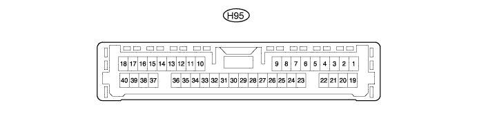
CHECK CLEARANCE WARNING ECU
Terminal No. (Symbol) Wiring Color Terminal Description Condition Specified Condition H95-1 (IG) - H95-22 (E) P - W-B Clearance sonar on/off switch signal Ignition switch ON, back sonar or clearance sonar switch on 11 to 14 V Ignition switch ON, back sonar or clearance sonar switch off Below 1 V H95-5 (SPD) - H95-22 (E) Y - W-B Vehicle speed signal Ignition switch ON, back sonar or clearance sonar switch on, vehicle speed signal input Pulse generation
(Frequency changes according to vehicle speed)
H95-6 (PKB) - H95-22 (E) P - W-B Parking brake switch signal Parking brake switch on Below 1 V Parking brake switch off 11 to 14 V H95-7 (PL) - H95-22 (E)* V - W-B Parking signal Ignition switch ON, shift lever in P 7 V or higher Ignition switch ON, shift lever not in P Below 1 V H95-9 (L4) - H95-22 (E) L - W-B Front corner sensor RH indicator signal Clearance warning indicator LED for front corner sensor RH illuminates Below 3 V H95-10 (E7) - H95-22 (E) W - W-B Front center sensor RH ground Always Below 1 Ω H95-11 (S7) - H95-10 (E7) R - W Front center sensor RH sensor signal
-
All conditions met:
-
-
Ignition switch ON, back sonar or clearance sonar switch on
-
Shift lever not in P (except Manual Transaxle) or R
-
Vehicle speed less than 10 km/h (6 mph)
-
Pulse generation
(See waveform 2)
H95-12 (E6) - H95-22 (E) W - W-B Front corner sensor LH ground Always Below 1 Ω H95-13 (S6) - H95-12 (E6) L - W Front corner sensor LH sensor signal
-
All conditions met:
-
-
Ignition switch ON, back sonar or clearance sonar switch on
-
Shift lever not in P (except Manual Transaxle) or R
-
Vehicle speed less than 10 km/h (6 mph) with shift lever not in P (except Manual Transaxle) or R
-
Pulse generation
(See waveform 2)
H95-15 (E4) - H95-22 (E) V -W-B Rear center sensor LH ground Always Below 1 Ω H95-16 (S4) - H95-15 (E4) P - V Rear center sensor RH sensor signal
-
All conditions met:
-
-
Ignition switch ON, back sonar or clearance sonar switch on
-
Shift lever in R
-
Pulse generation
(See waveform 2)
H95-17 (E1) - H95-22 (E) W - W-B Rear corner sensor RH ground Always Below 1 Ω H95-18 (S1) - H95-17 (E1) P - W Rear corner sensor RH sensor signal
-
All conditions met:
-
-
Ignition switch ON, back sonar or clearance sonar switch on
-
Shift lever in R
-
Pulse generation
(See waveform 2)
H95-19 (CBZ) - H95-20 (EF) SB - R Clearance warning buzzer signal When sonar detects obstacle (buzzer sounds) Pulse generation
(See waveform 1)
Buzzer not sounding 11 to 14 V H95-20 (EF) - Body ground R - Body ground Positive (+) terminal of clearance warning buzzer Always 11 to 14 V H95-22 (E) - Body ground W-B - Body ground ECU ground Always Below 1 Ω H95-23 (RL) - H95-22 (E) R - W-B Reverse signal Ignition switch ON, shift lever in R 7 V or higher Ignition switch ON, shift lever not in R Below 1 V H95-24 (TL) - H95-22 (E) Y - W-B Illumination signal Ignition switch ON, light control switch on 11 to 14 V Ignition switch ON, light control switch off Below 1 V H95-25 (MSDL) - H95-22 (E) R - W-B Clearance sonar switch illumination signal Ignition switch ON, back sonar or clearance sonar switch on Below 3 V H95-26 (L5) - H95-22 (E) Y - W-B Front corner sensor LH indicator signal Clearance warning indicator LED for front corner sensor LH illuminates Below 3 V H95-27 (L6) - H95-22 (E) B - W-B Front center sensor indicator signal Clearance warning indicator LED for front center sensor illuminates Below 3 V H95-28 (L1) - H95-22 (E) LG - W-B Rear corner sensor RH indicator signal Clearance warning indicator LED for rear corner sensor RH illuminates Below 3 V H95-29 (L2) - H95-22 (E) SB - W-B Rear corner sensor LH indicator signal Clearance warning indicator LED for rear corner sensor LH illuminates Below 3 V H95-30 (L3) - H95-22 (E) G - W-B Rear center sensor indicator signal Clearance warning indicator LED for rear center sensor illuminates Below 3 V H95-31 (L10) - H95-22 (E) R - W-B Vehicle LED indicator signal Clearance warning indicator LED for vehicle LED illuminates Below 3 V H95-33 (E5) - H95-22 (E) GR - W-B Front corner sensor RH ground Always Below 1 Ω H95-34 (S5) - H95-33 (E5) BR - GR Front corner sensor RH sensor signal
-
All conditions met:
-
-
Ignition switch ON, back sonar or clearance sonar switch on
-
Shift lever not in P (except Manual Transaxle) or R
-
Vehicle speed less than 10 km/h (6 mph) with shift lever not in P (except Manual Transaxle) or R
-
Pulse generation
(See waveform 2)
H95-35 (E8) - H95-22 (E) W - W-B Front center sensor LH ground Always Below 1 Ω H95-36 (S8) - H95-35 (E8) P - W Front center sensor LH sensor signal
-
All conditions met:
-
-
Ignition switch ON, back sonar or clearance sonar switch on
-
Shift lever not in P (except Manual Transaxle) or R
-
Vehicle speed less than 10 km/h (6 mph)
-
Pulse generation
(See waveform 2)
H95-37 (E2) - H95-22 (E) LG - W-B Rear corner sensor LH ground Always Below 1 Ω H95-38 (S2) - H95-37 (E2) L - LG Rear corner sensor LH sensor signal
-
All conditions met:
-
-
Ignition switch ON, back sonar or clearance sonar switch on
-
Shift lever in R
-
Pulse generation
(See waveform 2)
H95-39 (E3) - H95-22 (E) BR - W-B Rear center sensor RH ground Always Below 1 Ω H95-40 (S3) - H95-39 (E3) GR - BR Rear center sensor RH sensor signal
-
All conditions met:
-
-
Ignition switch ON, back sonar or clearance sonar switch on
-
Shift lever in R
-
Pulse generation
(See waveform 2)
-
*: except Manual Transaxle
-
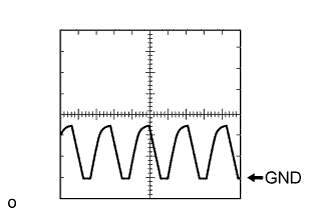
Using an oscilloscope, check waveform 1.
Table 1. Measurement Condition Item Content Terminal No. (Symbol) H95-19 (CBZ) - H95-20 (EF) Tool Setting 2 V/DIV., 0.2 msec./DIV. Condition When sonar detects obstacle (buzzer sounds) Tip:The amplitude of the waveform changes depending on the volume setting.
-
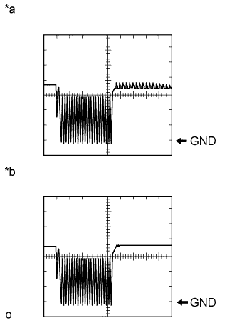
Using an oscilloscope, check waveform 2.
Table 2. Measurement Condition Item Content Terminal No. (Symbol) H95-11 (S7) - H95-10 (E7)
H95-13 (S6) - H95-12 (E6)
H95-16 (S4) - H95-15 (E4)
H95-18 (S1) - H95-17 (E1)
H95-34 (S5) - H95-33 (E5)
H95-36 (S8) - H95-35 (E8)
H95-38 (S2) - H95-37 (E2)
H95-40 (S3) - H95-39 (E3)
Tool Setting 2 V/DIV., 0.05 msec./DIV. Condition Ignition switch ON, back sonar or clearance sonar switch on Table 3. Text in Illustration *a Ultrasonic sensor is normal *b Open circuit in ultrasonic sensor
-