TOYOTA PARKING ASSIST-SENSOR SYSTEM Clearance Sonar Main Switch Circuit
DESCRIPTION
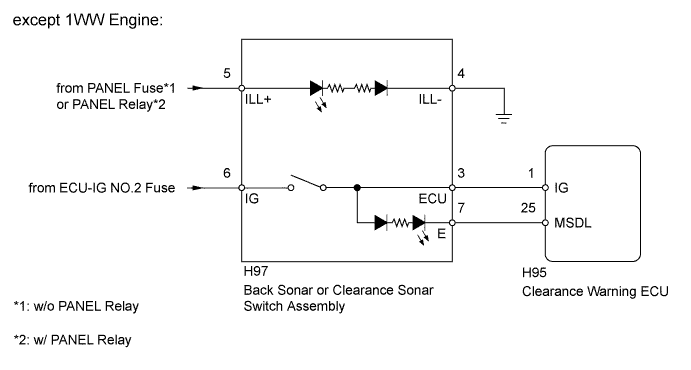
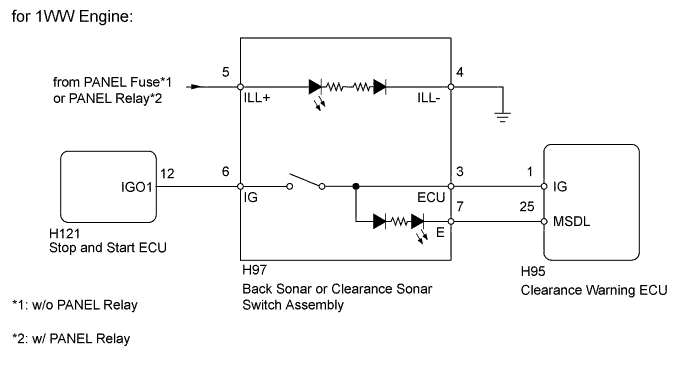
When the back sonar or clearance sonar switch assembly turns on, the on signal is input into the ECU.
WIRING DIAGRAM
INSPECTION PROCEDURE
Note
Inspect the fuses for circuits related to this system before performing the following inspection procedure.
PROCEDURE
-
CHECK SYMPTOMS
-
Check the symptoms.
Result Result Proceed to Back sonar or clearance sonar switch does not operate normally A Back sonar or clearance sonar switch operate normally, but the switch indicator does not illuminate A Back sonar or clearance sonar switch operate normally, but the indicator does not illuminate normally B
B 
INSPECT BACK SONAR OR CLEARANCE SONAR SWITCH ASSEMBLY Click here
A 
-
-
INSPECT BACK SONAR OR CLEARANCE SONAR SWITCH ASSEMBLY
-
Remove the back sonar or clearance sonar switch assembly Click here.
-
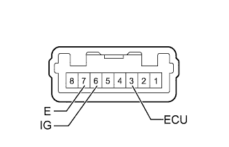
Measure the resistance according to the value(s) in the table below.
Standard Resistance Tester Connection Switch Condition Specified Condition 3 (ECU) - 6 (IG) Sonar switch on Below 1 Ω 3 (ECU) - 6 (IG) Sonar switch off 10 kΩ or higher -
Inspect the indicator operation.
OK Measurement Condition Specified Condition Battery positive (+) → Terminal 3 (ECU)
Battery negative (-) → Terminal 7 (E)
LED illuminates Result Result Proceed to OK (except 1WW Engine) A OK (for 1WW Engine) B NG C
B
CHECK HARNESS AND CONNECTOR (BACK SONAR OR CLEARANCE SONAR SWITCH - STOP AND START ECU) Click here
C 
REPLACE BACK SONAR OR CLEARANCE SONAR SWITCH ASSEMBLY Click here
A
-
-
CHECK HARNESS AND CONNECTOR (BACK SONAR OR CLEARANCE SONAR SWITCH - BATTERY)
-
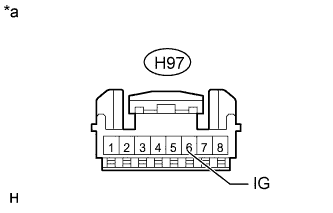
Text in Illustration *a Front view of wire harness connector
(to Back Sonar or Clearance Sonar Switch Assembly)
Disconnect the H97 back sonar or clearance sonar switch assembly connector.
-
Measure the voltage according to the value(s) in the table below.
Standard Voltage Tester Connection Switch Condition Specified Condition H97-6 (IG) - Body ground Ignition switch ON 11 to 14 V H97-6 (IG) - Body ground Ignition switch off Below 1 V
NG
REPAIR OR REPLACE HARNESS OR CONNECTOR
OK
-
-
CHECK HARNESS AND CONNECTOR (BACK SONAR OR CLEARANCE SONAR SWITCH - CLEARANCE WARNING ECU)
-
Disconnect the H97 back sonar or clearance sonar switch assembly connector.
-
Disconnect the H95 clearance warning ECU connector.
-
Measure the resistance according to the value(s) in the table below.
Standard Resistance Tester Connection Condition Specified Condition H97-3 (ECU) - H95-1 (IG) Always Below 1 Ω H97-7 (E) - H95-25 (MSDL) Always Below 1 Ω H97-3 (ECU) - Body ground Always 10 kΩ or higher H97-7 (E) - Body ground Always 10 kΩ or higher
NG
REPAIR OR REPLACE HARNESS OR CONNECTOR
OK 
PROCEED TO NEXT SUSPECTED AREA SHOWN IN PROBLEM SYMPTOMS TABLE Click here
-
-
CHECK HARNESS AND CONNECTOR (BACK SONAR OR CLEARANCE SONAR SWITCH - STOP AND START ECU)
-
Disconnect the H97 back sonar or clearance sonar switch assembly connector.
-
Disconnect the H121 stop and start ECU connector.
-
Measure the resistance according to the value(s) in the table below.
Standard Resistance Tester Connection Condition Specified Condition H97-6 (IG) - H121-12 (IGO1) Always Below 1 Ω H97-6 (IG) - Body ground Always 10 kΩ or higher
NG
REPAIR OR REPLACE HARNESS OR CONNECTOR
OK
-
-
CHECK HARNESS AND CONNECTOR (BACK SONAR OR CLEARANCE SONAR SWITCH - CLEARANCE WARNING ECU)
-
Disconnect the H97 back sonar or clearance sonar switch assembly connector.
-
Disconnect the H95 clearance warning ECU connector.
-
Measure the resistance according to the value(s) in the table below.
Standard Resistance Tester Connection Condition Specified Condition H97-3 (ECU) - H95-1 (IG) Always Below 1 Ω H97-7 (E) - H95-25 (MSDL) Always Below 1 Ω H97-3 (ECU) - Body ground Always 10 kΩ or higher H97-7 (E) - Body ground Always 10 kΩ or higher
NG
REPAIR OR REPLACE HARNESS OR CONNECTOR
OK
PROCEED TO NEXT SUSPECTED AREA SHOWN IN PROBLEM SYMPTOMS TABLE Click here
-
-
INSPECT BACK SONAR OR CLEARANCE SONAR SWITCH ASSEMBLY
-
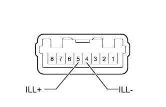
Remove the back sonar or clearance sonar switch assembly Click here.
-
Inspect the indicator operation.
OK Measurement Condition Specified Condition Battery positive (+) → Terminal 5 (ILL+)
Battery negative (-) → Terminal 4 (ILL-)
LED illuminates
NG
REPLACE BACK SONAR OR CLEARANCE SONAR SWITCH ASSEMBLY Click here
OK
-
-
CHECK HARNESS AND CONNECTOR (BACK SONAR OR CLEARANCE SONAR SWITCH - BATTERY)
-
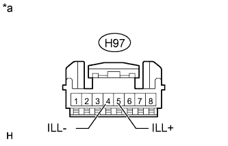
Text in Illustration *a Front view of wire harness connector
(to Back Sonar or Clearance Sonar Switch Assembly)
Disconnect the H97 back sonar or clearance sonar switch assembly connector.
-
Measure the voltage according to the value(s) in the table below.
Standard Voltage Tester Connection Switch Condition Specified Condition H97-5 (ILL+) - Body ground Ignition switch ON, light control switch tail or head 11 to 14 V H97-5 (ILL+) - Body ground Ignition switch off, light control switch off Below 1 V -
Measure the resistance according to the value(s) in the table below.
Standard Resistance Tester Connection Condition Specified Condition H97-4 (ILL-) - Body ground Always Below 1 Ω
NG
REPAIR OR REPLACE HARNESS OR CONNECTOR
OK
PROCEED TO NEXT SUSPECTED AREA SHOWN IN PROBLEM SYMPTOMS TABLE Click here
-