NAVIGATION SYSTEM Microphone Circuit between Radio Receiver and Extension Module
DESCRIPTION
This circuit sends a microphone voice signal from the extension module to the radio and display receiver assembly.
Using this circuit, the extension module disables the microphone function of the radio and display receiver assembly to receive a microphone voice signal from the telephone microphone assembly.
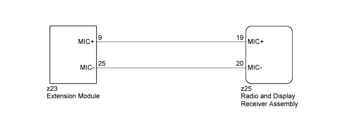
WIRING DIAGRAM
INSPECTION PROCEDURE
PROCEDURE
-
CHECK HARNESS AND CONNECTOR (RADIO AND DISPLAY RECEIVER ASSEMBLY - EXTENSION MODULE)
-
Disconnect the z25 radio and display receiver assembly connector.
-
Disconnect the z23 extension module connector.
-
Measure the resistance according to the value(s) in the table below.
Standard Resistance Tester Connection Condition Specified Condition z25-19 (MIC+) - z23-9 (MIC+) Always Below 1 Ω z25-20 (MIC-) - z23-25 (MIC-) Always Below 1 Ω z25-19 (MIC+) - Body ground Always 10 kΩ or higher z25-20 (MIC-) - Body ground Always 10 kΩ or higher
NG 
REPAIR OR REPLACE HARNESS OR CONNECTOR
OK 
PROCEED TO NEXT SUSPECTED AREA SHOWN IN PROBLEM SYMPTOMS TABLE Click here
-