MULTI-MEDIA INTERFACE ECU REMOVAL

-
PRECAUTION
Note
After turning the ignition switch off, waiting time may be required before disconnecting the cable from the battery terminal. Therefore, make sure to read the disconnecting the cable from the battery terminal notice before proceeding with work. Click here.
-
REMOVE BATTERY SERVICE HOLE COVER
-
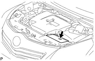
Remove the clip and battery service hole cover.
-
-
DISCONNECT CABLE FROM NEGATIVE BATTERY TERMINAL
Note
When disconnecting the cable, some systems need to be initialized after the cable is reconnected Click here.
-
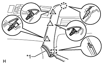
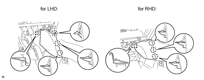
REMOVE INSTRUMENT PANEL FINISH PANEL END LH
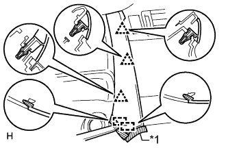
Text in Illustration *1 Protective Tape
-
for Automatic Air Conditioning System:
-
Put protective tape around the instrument panel finish panel end.
-
Using a moulding remover, detach the 3 clips and 2 guides, and remove the instrument panel finish panel end.
-
-
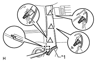
Text in Illustration *1 Protective Tape for Manual Air Conditioning System:
-
Put protective tape around the instrument panel finish panel end.
-
Using a moulding remover, detach the 3 clips and guide, and remove the instrument panel finish panel end.
-
-
-
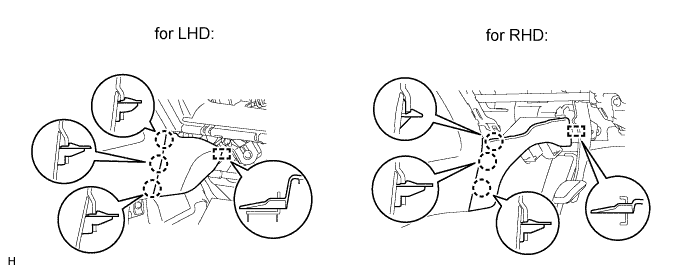
REMOVE INSTRUMENT PANEL FINISH PANEL END RH
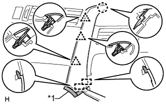
Text in Illustration *1 Protective Tape
-
for Automatic Air Conditioning System:
-
Put protective tape around the instrument panel finish panel end.
-
Using a moulding remover, detach the 3 clips, claw and 2 guides, and remove the instrument panel finish panel end.
-
-
Text in Illustration *1 Protective Tape for Manual Air Conditioning System:
-
Put protective tape around the instrument panel finish panel end.
-
Using a moulding remover, detach the 3 clips, claw and guide, and remove the instrument panel finish panel end.
-
-
-
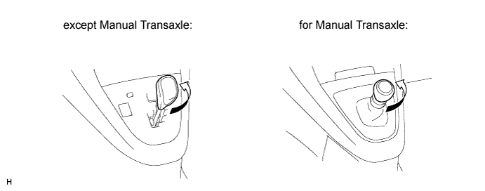
REMOVE SHIFT LEVER KNOB SUB-ASSEMBLY
-
Twist the shift lever knob in the direction indicated by the arrow and remove it.
-
-
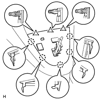
REMOVE POSITION INDICATOR HOUSING ASSEMBLY (except Manual Transaxle)
-
Detach the 5 claws and 3 clips.
-
Disconnect the connector and remove the position indicator housing.
-
-
REMOVE SHIFTING HOLE COVER (for Manual Transaxle)
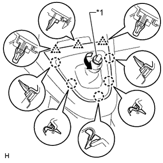
Text in Illustration *1 T Washer
-
Twist the T washer in the direction indicated by the arrow and remove it.
-
Remove the knob spring.
-
Detach the 5 claws and 3 clips, and remove the shifting hole cover.
-
-
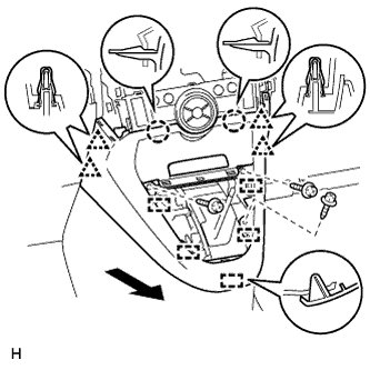
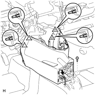
REMOVE LOWER CENTER INSTRUMENT PANEL FINISH PANEL
-
for Automatic Air Conditioning System:
-
Remove the 3 screws <C>.
-
Detach the 2 claws, 4 clips and 5 guides, and remove the lower center instrument panel finish panel.
Tech Tips
If the 2 claws shown in the illustration are difficult to detach, detach the 4 clips of the air conditioning control and remove the lower center instrument panel finish panel together with the air conditioning control.
-
-
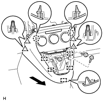
for Manual Air Conditioning System:
-
Remove the 3 screws <C>.
-
Detach the 4 clips, 2 claws and 5 guides, and remove the lower center instrument panel finish panel.
-
-
-
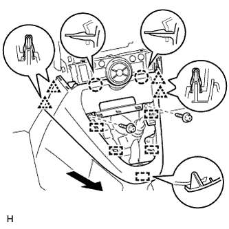
REMOVE LOWER CENTER INSTRUMENT PANEL FINISH PANEL (for Manual Transaxle)
-
for Automatic Air Conditioning System:
-
Remove the 2 screws <C>.
-
Detach the 2 claws, 4 clips and 5 guides, and remove the lower center instrument panel finish panel.
Tech Tips
If the 2 claws shown in the illustration are difficult to detach, detach the 4 clips of the air conditioning control and remove the lower center instrument panel finish panel together with the air conditioning control.
-
-
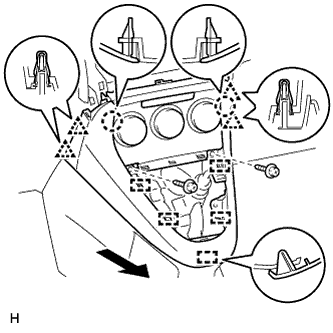
for Manual Air Conditioning System:
-
Remove the 2 screws <C>.
-
Detach the 4 clips, 2 claws and 5 guides, and remove the lower center instrument panel finish panel.
-
-
-
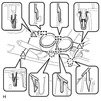
REMOVE UPPER CONSOLE PANEL
-
Detach the 2 claws, 3 clips and 3 guides.
-
Disconnect the connectors and remove the upper console panel.
-
-
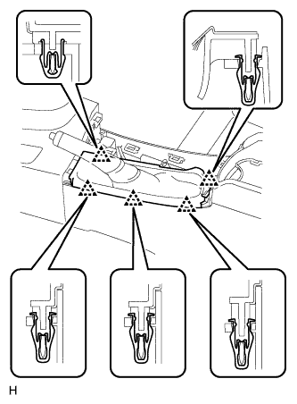
REMOVE PARKING BRAKE HOLE COVER SUB-ASSEMBLY
-
Detach the 5 clips and remove the parking brake hole cover.
-
-
REMOVE CONSOLE BOX POCKET
-
Remove the console box pocket.
-
-
REMOVE CONSOLE BOX CARPET
-
Remove the console box carpet.
-
-
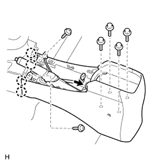
REMOVE BOX PANEL SUB-ASSEMBLY
-
w/o Console Box Lid:
-
Remove the 2 screws and 4 bolts.
-
Detach the 4 claws.
-
Disconnect the connector and remove the box panel.
-
-
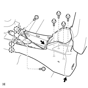
w/ Console Box Lid:
-
Remove the 2 screws and 4 bolts.
-
Detach the 4 claws.
-
Disconnect the 2 connectors and remove the box panel.
-
-
-
REMOVE FRONT NO. 1 CONSOLE BOX INSERT
-
Detach the 3 claws and guide, and remove the front No. 1 console box insert.
-
-
REMOVE FRONT NO. 2 CONSOLE BOX INSERT
-
Detach the 3 claws and guide, and remove the front No. 2 console box insert.
-
-
REMOVE LOWER NO. 1 INSTRUMENT PANEL FINISH PANEL
-
Remove the screw <D>.
-
Disconnect the connector.
-
Detach the 4 clips and remove the lower No. 1 instrument panel finish panel.
-
-
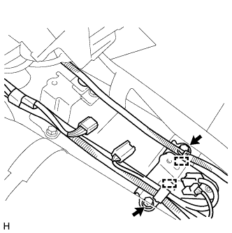
REMOVE MULTI-MEDIA INTERFACE ECU WITH BRACKET
-
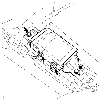
Disconnect the 2 connectors.
-
Remove the 2 bolts and multi-media interface ECU with bracket.
-
-
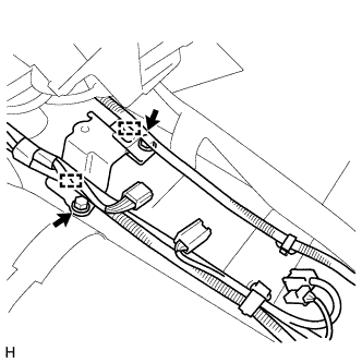
REMOVE NO. 1 CONSOLE BOX MOUNTING BRACKET
-
Detach the 2 clamps.
-
Remove the 2 bolts and No. 1 console box mounting bracket.
-
-
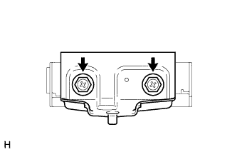
REMOVE NO. 3 MULTI-MEDIA INTERFACE BRACKET
-
Detach the 2 clamps.
-
Remove the 2 bolts and No. 3 multi-media interface bracket.
-
-
REMOVE NO. 2 MULTI-MEDIA INTERFACE BRACKET
-
Remove the 2 bolts and No. 2 multi-media interface bracket.
-
-
REMOVE NO. 1 MULTI-MEDIA INTERFACE BRACKET
-
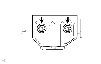
Remove the 2 bolts and No. 1 multi-media interface bracket.
-