STOP LIGHT SWITCH INSTALLATION

-
INSTALL STOP LIGHT SWITCH MOUNTING ADJUSTER
-
Attach the 2 claws to install a new stop light switch mounting adjuster.
-
-
INSTALL STOP LIGHT SWITCH ASSEMBLY
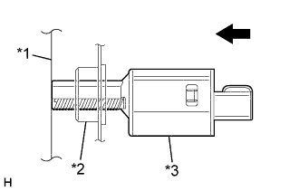
Text in Illustration *1 Brake Pedal *2 Stop Light Switch Mounting Adjuster *3 Stop Light Switch Assembly
-
Install the stop light switch assembly to the adjuster until the switch body slightly touches the brake pedal.
Note
Do not depress the brake pedal.
-
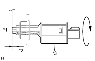
Text in Illustration *1 Shaft *2 1.5 to 2.5 mm (0.0590 to 0.0984 in.) *3 Stop Light Switch Assembly Rotate the stop light switch assembly clockwise so that the clearance is between 1.5 and 2.5 mm (0.0590 to 0.0984 in.) as shown in the illustration.
- Torque:
- 1.5 N*m { 15 kgf*cm, 13 in.*lbf }
Note
Do not depress the brake pedal.
-
Check the stop light switch assembly clearance.
Stop light switch clearance 1.5 to 2.5 mm (0.0590 to 0.0984 in.) -
Connect the connector to the stop light switch assembly.
-
-
INSTALL NO. 1 INSTRUMENT PANEL UNDER COVER SUB-ASSEMBLY
-
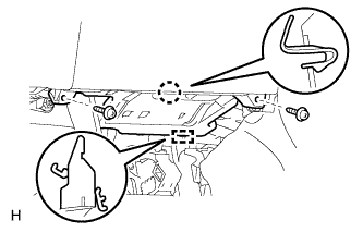
Attach the claw and guide to install the No. 1 instrument panel under cover.
-
Install the 2 screws <A>.
-