DESCRIPTION
The headlight leveling ECU receives the vehicle speed signal from the combination meter.
-
A voltage of 12 V or 5 V is output from each ECU connected to the combination meter and then input to the combination meter. The signal is changed to a pulse signal at the transistor in the combination meter. Each ECU connected to the combination meter controls its respective system based on this pulse signal.
-
If a short occurs in any of the ECUs connected to the combination meter, or in the wire harness of an ECU connected to the combination meter, the systems in the diagram below will not operate normally.
| DTC Code | DTC Detection Condition | Trouble Area |
|---|---|---|
| B2415 | One of the following conditions is met:
|
|
INSPECTION PROCEDURE
PROCEDURE
- Click here
CHECK COMBINATION METER SYSTEM
-
Inspect the circuits that send vehicle speed signals to this system in the meter system (Click here).
Tip:During inspection for the meter section, if there is an instruction that indicates to proceed to the next suspected area, proceed to the next step.
- NEXTClick here
-
- Click here
CHECK HARNESS AND CONNECTOR (COMBINATION METER ASSEMBLY - HEADLIGHT LEVELING ECU ASSEMBLY)
-
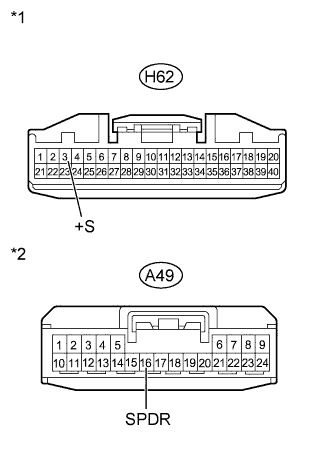
Disconnect the H62 combination meter connector.
-
Disconnect the A49 headlight leveling ECU connector.
-
Measure the resistance according to the value(s) in the table below.
Standard Resistance Tester Connection Condition Specified Condition H62-3 (+S) - A49-16 (SPDR) Always Below 1 Ω Table 1. Text in Illustration *1 Front view of wire harness connector
(to Combination Meter Assembly)
*2 Front view of wire harness connector
(to Headlight Leveling ECU Assembly)
Table 2. Result Result Proceed to OK (for LHD) A OK (for RHD) B NG C
-
- Click here
REPLACE HEADLIGHT LEVELING ECU ASSEMBLYClick here
- Click here
REPLACE HEADLIGHT LEVELING ECU ASSEMBLYClick here
- Click here
REPAIR OR REPLACE HARNESS OR CONNECTOR