LIGHTING SYSTEM TERMINALS OF ECU

-
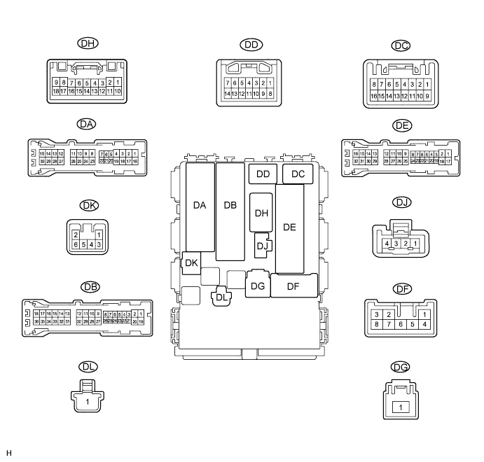
CHECK MAIN BODY ECU (INSTRUMENT PANEL JUNCTION BLOCK ASSEMBLY)
-
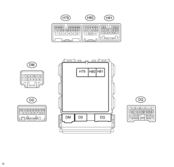
Disconnect the DB, DE, DF and H80 ECU connectors.
-
Measure the resistance and voltage according to the value(s) in the table below.
Terminal No. (Symbol) Wiring Color Terminal Description Condition Specified Condition DB-30 (BECU) - Body ground W - Body ground Battery power supply Always 11 to 14 V DF-5 (ACC) - Body ground W - Body ground ACC power supply Ignition switch ACC 11 to 14 V Ignition switch off Below 1 V DE-28 (GND1) - Body ground W-B - Body ground Ground Always Below 1 Ω H80-4 (GND2) - Body ground W-B - Body ground Ground Always Below 1 Ω If the result is not as specified, there may be a malfunction on the wire harness side.
-
Reconnect the DB, DE, DF and H80 ECU connectors.
-
Measure the voltage according to the value(s) in the table below.
Terminal No. (Symbol) Wiring Color Terminal Description Condition Specified Condition DJ-4 (HU) - DE-28 (GND1) P - W-B Dimmer switch high signal input Dimmer switch in high Below 1 V Dimmer switch in low 11 to 14 V H79-3 (DRLE) - DE-28 (GND1)*1,*2
H81-14 (DRLE) - DE-28 (GND1)*1,*3
W - W-B DRL relay drive output Daytime running light on Below 1 V Daytime running light off 11 to 14 V H79-20 (HRLY) - DE-28 (GND1) B - W-B H-LP relay drive output Light control switch in head Below 1 V Light control switch not in head 11 to 14 V H79-21 (TAIL) - DE-28 (GND1) W - W-B Light control switch tail signal input Light control switch in tail or head Below 1 V Light control switch in neither tail nor head 11 to 14 V H79-22 (HF) - DE-28 (GND1) R - W-B Dimmer switch high flash signal input Dimmer switch in high flash position Below 1 V Dimmer switch not in high flash position 11 to 14 V H80-11 (RFGO) - DE-28 (GND1) GR - W-B Rear fog light relay drive output Light control switch in head and rear fog light switch on Below 1 V Light control switch in head and rear fog light switch off 11 to 14 V H80-12 (DIM) - DE-28 (GND1) LG - W-B Dimmer relay drive output Dimmer switch in high or high flash Below 1 V Dimmer switch not in high or high flash 11 to 14 V H80-15 (CLTS) - DE-28 (GND1)*4 V - W-B Automatic light control sensor signal input Ignition switch off Below 1 V Automatic light control system operates Pulse generation
(See waveform 1)
H81-9 (RFOG) - DE-28 (GND1) SB - W-B Rear fog light switch input Rear fog light switch on Below 1 V Rear fog light switch off 11 to 14 V H81-12 (HEAD) - DE-28 (GND1) L - W-B Light control switch head signal input Light control switch in head Below 1 V Light control switch not in head 11 to 14 V H81-13 (FFOG) - DE-28 (GND1)*5 B - W-B Front fog light switch input Front fog light switch on Below 1 V Front fog light switch off 11 to 14 V H81-17 (FFGO) - DE-28 (GND1)*5 R - W-B Front fog light relay drive output Light control switch in tail and front fog light switch on Below 1 V Front fog light switch off 11 to 14 V H81-18 (A) - DE-28 (GND1)*4 V - W-B Light control switch AUTO signal input Light control switch in AUTO Below 1 V Light control switch not in AUTO 11 to 14 V DG-1 (TRLY) - DE-28 (GND1) W - W-B Battery power supply Always 11 to 14 V DC-5 (PKB) - DE-28 (GND1)*1 P - W-B Parking brake switch input Parking brake switch on Below 1 V Parking brake switch off 11 to 14 V DB-33 (TRLY) - DE-28 (GND1) GR - W-B Clearance light LH signal output Light control switch in tail position 11 to 14 V Light control switch not in tail position Below 1 V DB-15 (TRLY) - DE-28 (GND1) G - W-B Clearance light RH signal output Light control switch in tail position 11 to 14 V Light control switch not in tail position Below 1 V DA-29 (TRLY) - DE-28 (GND1) G - W-B Taillight signal output Light control switch in tail position 11 to 14 V Light control switch not in tail position Below 1 V DS-17 (HAZ) - DE-28 (GND1) B - W-B Hazard warning signal switch input Hazard warning signal switch on Below 1 V Hazard warning signal switch off 11 to 14 V
-
*1: w/ Daytime Running Light
-
*2: for LHD
-
*3: for RHD
-
*4: w/ Automatic Light Control System
-
*5: w/ Front Fog Light
-
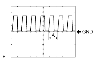
Waveform 1
Item Content Terminal No. (Symbol) H80-15 (CLTS) - DE-28 (GND1) Tool setting 5 V/DIV., 5 ms./DIV. Condition Ignition switch ON
Headlight dimmer switch AUTO
Rain sensor covered with a hand → Rain sensor exposed to ambient light
Tech Tips
If the ambient light becomes brighter, width A becomes narrower.
-
-
-
CHECK HEADLIGHT LEVELING ECU (for HID Headlight)

-
Disconnect the A49 ECU connector.
-
Measure the voltage and resistance according to the value(s) in the table below.
Terminal No. (Symbol) Wiring Color Terminal Description Condition Specified Condition A49-1 (IG) - Body ground G - Body ground Ignition power supply Ignition switch off Below 1 V Ignition switch ON 11 to 14 V A49-9 (E1) - Body ground W-B - Body ground Ground Always Below 1 Ω If the result is not as specified, there may be a malfunction on the wire harness side.
-
Reconnect the A49 ECU connector.
-
Measure the resistance and voltage according to the value(s) in the table below.
Terminal No. (Symbol) Wiring Color Terminal Description Condition Specified Condition A49-3 (B2) - A49-9 (E1) B - W-B Low beam headlight signal input Low beam headlights on Below 1 V Low beam headlights off 11 to 14 V A49-5 (PRST) - A49-9 (E1) GR - W-B Initialization signal input Terminal LVL and terminal GND of DLC3 connected Below 1 V Terminal LVL and terminal GND of DLC3 not connected Approximately 5 V A49-6 (WNG) - A49-9 (E1) GR - W-B Warning indicator drive output Warning indicator on 11 to 14 V Warning indicator off Below 1 V A49-10 (RHT) - A49-9 (E1) LG - W-B Leveling motor RH power supply Ignition switch off Below 1 V Ignition switch ON 11 to 14 V A49-11 (LHT) - A49-9 (E1) W - W-B Leveling motor LH power supply Ignition switch off Below 1 V Ignition switch ON 11 to 14 V A49-12 (SBR) - A49-21 (SGR) R - BR Rear height control sensor power supply Ignition switch off Below 1 V Ignition switch ON 4.75 to 5.25 V A49-16 (SPDR) - A49-9 (E1) V - W-B Vehicle speed signal input Vehicle is driven at approximately 20 km/h (12 mph) Pulse generation
(See waveform 1)
A49-17 (RH+) - A49-9 (E1) P - W-B Leveling motor RH operation signal input With low beam headlights on, vehicle height not changed Below 1 V With low beam headlights on, vehicle height changed and maintained for more than 3 seconds 1.0 to 14.4 V A49-18 (LH+) - A49-9 (E1) BR-W - W-B Leveling motor LH operation signal input With low beam headlights on, vehicle height not changed Below 1 V With low beam headlights on, vehicle height changed and maintained for more than 3 seconds 1.0 to 14.4 V A49-19 (SHRL) - A49-21 (SGR) Y - BR Rear height control sensor signal input Ignition switch off Below 1 V Ignition switch ON 0.5 to 4.5 V A49-21 (SGR) - A49-9 (E1) BR - W-B Rear height control sensor ground Always Below 1 Ω A49-23 (RH-) - A49-9 (E1) W-B - W-B Leveling motor RH ground Always Below 1 Ω A49-24 (LH-) - A49-9 (E1) B - W-B Leveling motor LH ground Always Below 1 Ω
-
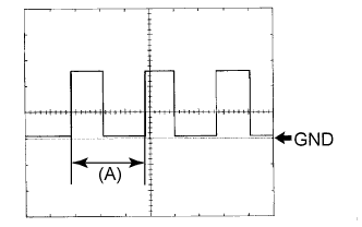
Waveform 1
Item Content Terminal No. (Symbol) A49-16 (SPDR) - A49-9 (E1) Tool setting 5 V/DIV., 20 ms./DIV. Condition Vehicle is driven at approximately 20 km/h (12 mph) Tech Tips
When the system is functioning normally, one wheel revolution generates 4 pulses. As the vehicle speed increases, the width indicated by (A) in the illustration narrows.
-
-