LIGHTING SYSTEM DRL Relay Circuit
DESCRIPTION
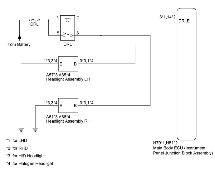
The main body ECU controls the daytime running lights.
WIRING DIAGRAM
INSPECTION PROCEDURE
Note
Inspect the fuses and bulbs for circuits related to this system before performing the following inspection procedure.
PROCEDURE
-
PERFORM ACTIVE TEST USING INTELLIGENT TESTER (DRL RELAY)
-
Using the intelligent tester, perform the Active Test Click here.
Main Body Tester Display Test Part Control Range Diagnostic Note Daytime Running Light Daytime running light ON / OFF - OK DRL relay operates (daytime running lights illuminate).
NG 
INSPECT DRL RELAY Click here
OK 
REPLACE MAIN BODY ECU (INSTRUMENT PANEL JUNCTION BLOCK ASSEMBLY)
-
-
INSPECT DRL RELAY
-
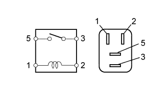
Remove the DRL relay from the No. 4 relay block.
-
Measure the resistance according to the value(s) in the table below.
Standard Resistance Tester Connection Condition Specified Condition 3 - 5 Battery voltage not applied between terminals 1 and 2 10 kΩ or higher 3 - 5 Battery voltage applied between terminals 1 and 2 Below 1 Ω
NG 
REPLACE DRL RELAY
OK 
-
-
CHECK HARNESS AND CONNECTOR (BATTERY - DRL RELAY)
-
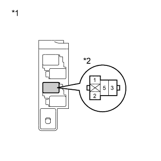
Text in Illustration *1 No. 4 Relay Block *2 DRL Relay Remove the DRL relay from the No. 4 relay block.
-
Measure the voltage according to the value(s) in the table below.
Standard Voltage Tester Connection Condition Specified Condition DRL relay terminal 1 - Body ground Always 11 to 14 V DRL relay terminal 5 - Body ground Always 11 to 14 V
NG
REPAIR OR REPLACE HARNESS OR CONNECTOR
OK
-
-
CHECK HARNESS AND CONNECTOR (DRL RELAY - MAIN BODY ECU)
-
Remove the DRL relay from the No. 4 relay block.
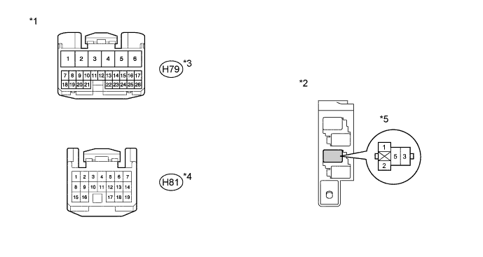
Text in Illustration *1 Front view of wire harness connector
(to Main Body ECU)
*2 No. 4 Relay Block *3 for LHD *4 for RHD *5 DRL Relay - - -
Disconnect the H79*1 or H81*2 main body ECU connector.
-
*1: for LHD
-
*2: for RHD
-
-
Measure the resistance according to the value(s) in the table below.
Standard Resistance for LHD: Tester Connection Condition Specified Condition DRL relay terminal 2 - H79-3 (DRLE) Always Below 1 Ω H79-3 (DRLE) - Body ground Always 10 kΩ or higher for RHD: Tester Connection Condition Specified Condition DRL relay terminal 2 - H81-14 (DRLE) Always Below 1 Ω H81-14 (DRLE) - Body ground Always 10 kΩ or higher
NG
REPAIR OR REPLACE HARNESS OR CONNECTOR
OK
PROCEED TO NEXT SUSPECTED AREA SHOWN IN PROBLEM SYMPTOMS TABLE Click here
-