WASHER MOTOR (for Rear Side) INSTALLATION

-
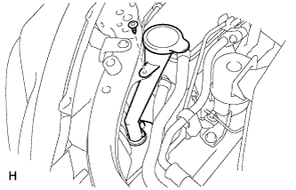
INSTALL REAR WASHER MOTOR ASSEMBLY
-
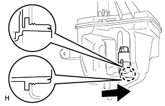
Install the rear washer motor assembly to the packing of the washer jar.
-
-
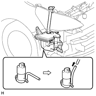
INSTALL WASHER JAR
-
w/o Headlight Cleaner System:
-
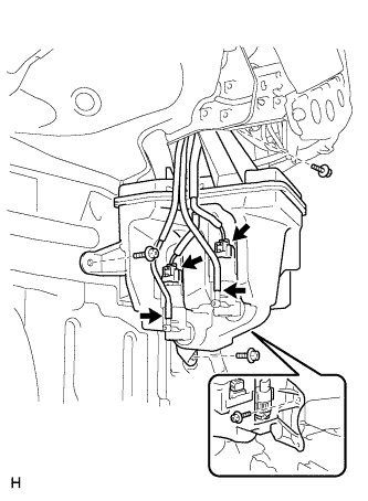
Install the washer jar with the 4 screws.
- Torque:
- 5.5 N*m { 56 kgf*cm, 49 in.*lbf }
-
Connect the 2 connectors.
-
Connect the 2 washer hoses to the washer motor and pump assemblies.
-
-
w/ Headlight Cleaner System:
-
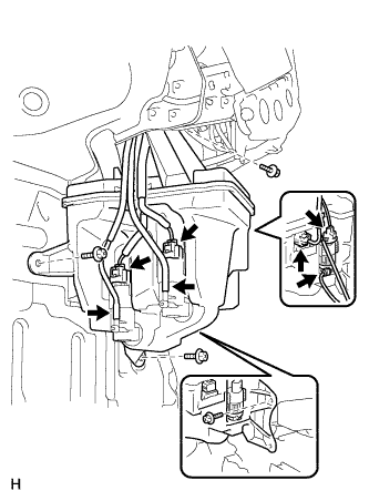
Install the washer jar with the 4 screws.
- Torque:
- 5.5 N*m { 56 kgf*cm, 49 in.*lbf }
-
Connect the 4 connectors.
-
Connect the 3 washer hoses to the washer motor and pump assemblies.
-
-
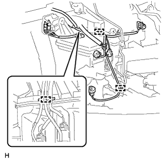
Attach the 3 clamps.
-
Install the clip.
-
-
FILL WASHER JAR WITH WASHER FLUID
-
Connect the washer hose to the hose of the windshield washer motor and pump assembly and fill the washer jar with washer fluid.
-
-
INSTALL FRONT FENDER LINER RH
-
Install the fender liner Click here.
-
-
INSTALL FRONT BUMPER COVER
-
Install the front bumper cover Click here.
-
-
INSTALL RADIATOR SUPPORT OPENING COVER
-
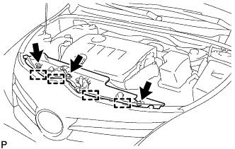
Attach the 4 hooks to install the radiator support opening cover.
-
Install the 3 clips.
-
-
PREPARATION FOR FOG LIGHT AIMING (w/ Fog Light)
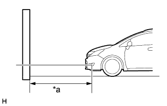
Text in Illustration *a 25 m or 3 m
-
Prepare the vehicle.
-
Place the vehicle in a location that is dark enough to clearly observe the cutoff line. The cutoff line is a distinct line, below which light from the fog lights can be observed and above which it cannot.
-
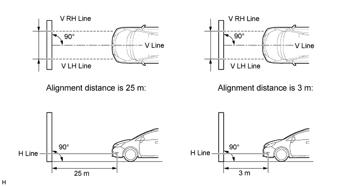
Place the vehicle at a 90° angle to the wall.
-
Create a 25 m (82 ft.) distance between the vehicle (fog light bulb center) and the wall.
-
Make sure that the vehicle is on a level surface.
-
Bounce the vehicle up and down to settle the suspension.
Note
A distance of 25 m (82 ft.) between the vehicle (fog light bulb center) and the wall is necessary for proper aim adjustment. If unavailable, secure a distance of exactly 3 m (9.84 ft.) for the check and adjustment. (The target zone will change with the distance, so follow the instructions in the illustration.)
-
-
Prepare a piece of thick white paper approximately 2.0 m (6.56 ft.) (height) x 4.0 m (13.1 ft.) (width) to use as a screen.
-
Draw a vertical line down the center of the screen (V line).
-
Set the screen as shown in the illustration.
Tech Tips
-
Stand the screen perpendicular to the ground.
-
Align the V line on the screen with the center of the vehicle.
-
-
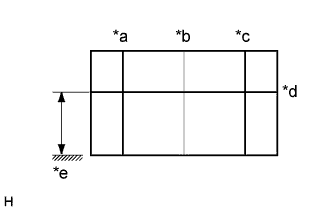
Text in Illustration *a V LH Line *b V Line *c V RH Line *d H Line *e Ground Draw base lines (H, V LH and V RH lines) on the screen as shown in the illustration.
Tech Tips
Mark the fog light bulb center marks on the screen. If the center mark cannot be observed on the fog light, use the center of the fog light bulb or the manufacturer's name marked on the fog light as the center mark.
-
H Line (Fog light height):
Draw a horizontal line across the screen so that it passes through the center marks. The H line should be at the same height as the fog light bulb center marks of the fog lights.
-
V LH Line, V RH Line (Center mark position of left-hand (LH) and right-hand (RH) fog lights):
Draw 2 vertical lines so that they intersect the H line at each center mark.
-
-
-
INSPECT FOG LIGHT AIMING (w/ Fog Light)
-
Cover the fog light or disconnect the connector of the fog light on the opposite side to prevent light from the fog light that is not being inspected from affecting the fog light aiming inspection.
Note
Do not keep the fog light covered for more than 3 minutes. The fog light lens is made of synthetic resin, which may melt or be damaged due to excessive heat.
-
Start the engine.
-
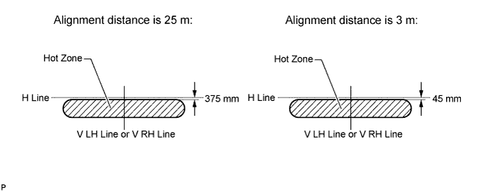
Turn on the fog light and check if the cutoff line falls within the specified area in the following illustration.
Tech Tips
-
If the alignment distance is 25 m (82 ft.):
The upper edge of the hot zone for the fog light should be 375 mm (14.8 in.) below the H line.
-
If the alignment distance is 3 m (9.84 ft.):
The upper edge of the hot zone for the fog light should be 45 mm (1.77 in.) below the H line.
-
-
-
ADJUST FOG LIGHT AIMING (w/ Fog Light)
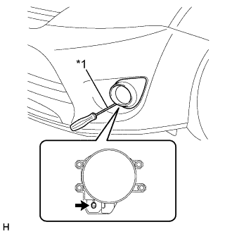
Text in Illustration *1 Aiming Screw
-
Adjust the aim vertically.
Adjust the aim of each fog light to the specified range by turning the aiming screw with a screwdriver.
Note
The final turn of the aiming screw should be made in the clockwise direction. If the screw is tightened excessively, loosen it, and then retighten it so that the final turn of the screw is in the clockwise direction.
Tech Tips
If it is not possible to correctly adjust fog light aim, check the bulb, fog light unit and fog light unit reflector installation.
-