WIPER AND WASHER SYSTEM (w/o Rain Sensor) SYSTEM DESCRIPTION

-
WASHER-LINKED OPERATION
-
When the front wiper washer switch is in the off position and the washer switch is turned on for approximately 0.1 seconds or more, the wipers start on LO at the same time as the washer fluid is sprayed.
Depending on the amount of time for which the washer switch is turned on, the washer-linked operation is performed as follows after the switch is turned off.
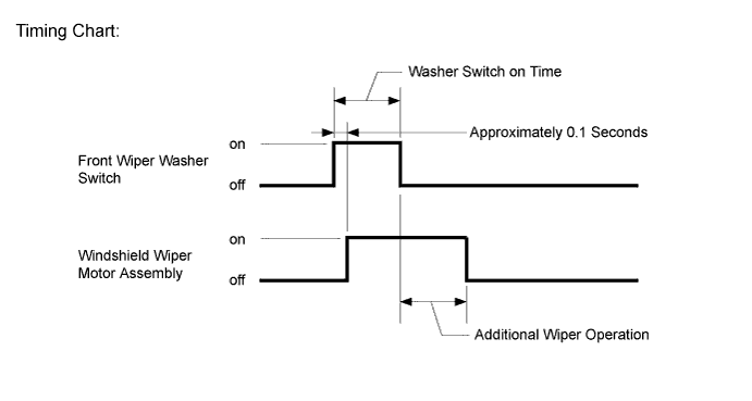
Washer Switch on Time Additional Wiper Operation 0.2 sec. or less None Between 0.2 sec. and 1.5 sec. 1 time 1.5 sec. or more 3 times
-
-
INTERMITTENT OPERATION
-
The system operates the front wipers at approximately 1.6 to 10.7 second intervals when the front wiper switch is turned to the INT position. The intermittent time can be adjusted from 1.6 to 10.7 seconds by using the intermittent time adjust dial.
-
If the front wiper switch is turned to the INT position, current flows from the already charged capacitor C1 through terminals INT1 and INT2 of the front wiper switch to Tr1 (transistor). When Tr1 turns on, current flows from terminal +S of the front wiper switch to terminal +1 of the front wiper switch, to terminal +1 of the wiper motor, to the wiper motor and finally to ground, causing the wiper motor to operate. At the same time, current flows from capacitor C1 to terminal INT1 of the front wiper switch and then INT2. When the current flow from capacitor C1 ends, Tr1 turns off to turn off the relay contact and halt the wiper motor.
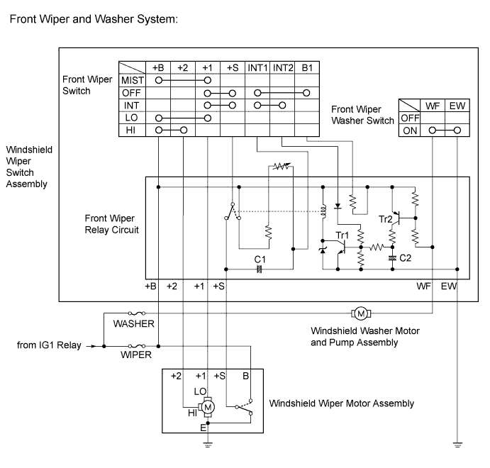
When the relay contact turns off, capacitor C1 begins to charge again and Tr1 remains off until charging has been completed. This period corresponds to the intermittent time. When capacitor C1 is fully charged, Tr1 turns on and then the relay contact turns on, causing the motor to operate again. This cycle is the intermittent operation.
The intermittent time can be adjusted by using the intermittent time adjust dial (variable resistor) to change the charge time of capacitor C1.
-
-
REAR WIPER INTERMITTENT OPERATION
-
When the rear wiper switch is turned to the INT position, current flows from the capacitor of the intermittent operation control circuit to turn on the transistor. Current flows from terminal +B of the rear wiper relay to the relay coil, to the transistor, to terminal C1 of the rear wiper relay, to terminal C1R of the rear wiper control switch and finally to ground, causing the relay contact to turn on.
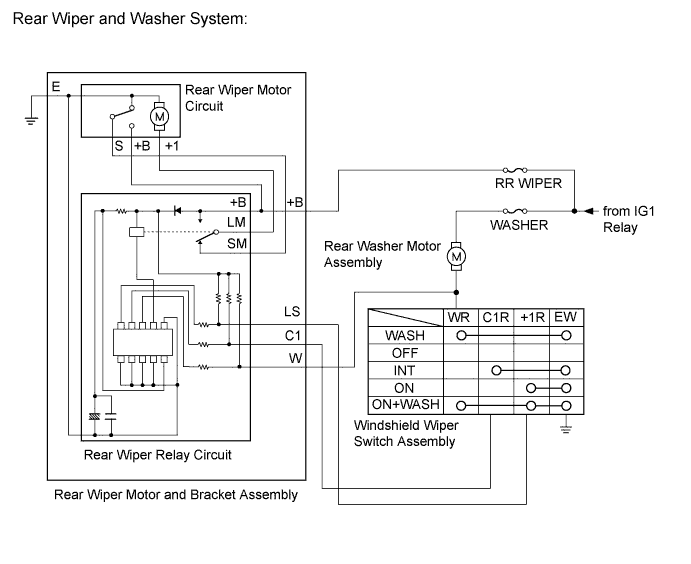
When the relay contact turns on, current flows from terminal +B of the rear wiper relay to the relay contact, to terminal LM of the rear wiper relay, to terminal +1 of the rear wiper motor, to the rear wiper motor and finally to ground, causing the rear wiper motor to operate. The transistor turns off immediately after the rear wiper motor operation as the current flow from the capacitor ends, causing the relay contact to turn off.
Even when the relay contact turns off, current flows from terminal +B of the rear wiper motor to the relay contact in the rear wiper motor, to terminal S of the rear wiper motor, to terminal SM of the rear wiper relay, to the contact of the rear wiper relay, to terminal LM of the rear wiper relay, to terminal +1 of the rear wiper motor and finally to ground, causing the rear wiper motor to operate, until the rear wiper motor stops at the automatic stop position. The rear wiper motor stops at the automatic stop position as the relay contact in the rear wiper motor turns off.
The capacitor in the intermittent operation control circuit is charged in approximately 12 seconds after the current flow ends. After the charge is completed, current starts flowing again to turn on the transistor, causing the relay contact to turn on.
This cycle of current flow and charging described above is the intermittent operation.
-
-
HEADLIGHT CLEANER SYSTEM (w/ Headlight Cleaner System)
-
The headlight cleaner system operates for a specified period of time when the headlights are on (the ignition switch is ON) and the headlight cleaner switch is turned on.
-
for HID Headlight:
The headlight cleaner system operates when the headlights are on (the ignition switch is ON) and the windshield wiper switch assembly (windshield washer switch) is turned on. However, the headlight cleaner system only operates when the windshield wiper switch assembly (windshield washer switch) is turned on the first time. After that, the headlight cleaner system cannot be operated with the windshield wiper switch assembly (windshield washer switch) until the ignition switch is turned off and then turned to ON.
-