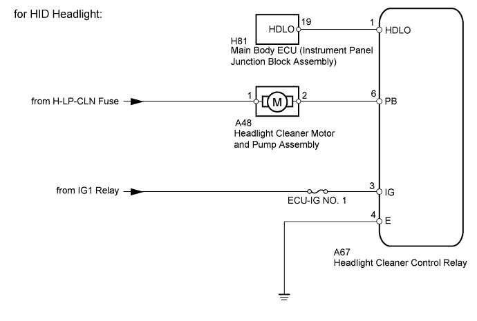
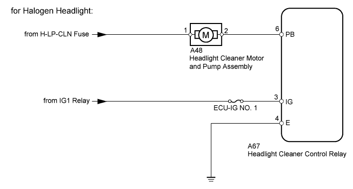
WIPER AND WASHER SYSTEM (w/ Rain Sensor) Headlight Cleaner Motor and Relay Circuit
DESCRIPTION
This circuit provides power to the headlight cleaner control relay.
The headlight cleaner control relay sends the signal from the headlight cleaner switch assembly, etc. to the headlight cleaner motor and pump assembly to operate the headlight cleaner system.
WIRING DIAGRAM
INSPECTION PROCEDURE
Note
Inspect the fuses for circuits related to this system before performing the following inspection procedure.
PROCEDURE
-
CHECK HEADLIGHT TYPE
-
Check the headlight type.
Result Result Proceed to HID Headlight A Halogen Headlight B
B 
CHECK HARNESS AND CONNECTOR (HEADLIGHT CLEANER MOTOR - BATTERY) Click here
A 
-
-
PERFORM ACTIVE TEST USING INTELLIGENT TESTER (HEADLIGHT CLEANER OPERATION)
-
Connect the intelligent tester to the DLC3.
-
Turn the ignition switch to ON.
-
Turn the front wiper washer switch (windshield wiper switch assembly) on.
-
Turn the intelligent tester on.
-
Enter the following menus: Body / Main Body / Active Test.
-
According to the display on the intelligent tester, perform the Active Test.
Main Body Tester Display Test Part Control Range Diagnostic Note Head Light Cleaner Headlight cleaner operation ON/OFF - Tech Tips
The headlight cleaner system only operates when the front wiper washer switch (windshield wiper switch assembly) is turned on the first time. After that, the headlight cleaner system cannot be operated with the front wiper washer switch (windshield wiper switch assembly) until the ignition switch is turned off and then turned to ON.
OK Headlight cleaner operates.
NG
CHECK HARNESS AND CONNECTOR (HEADLIGHT CLEANER MOTOR - BATTERY) Click here
OK
-
-
CHECK HARNESS AND CONNECTOR (HEADLIGHT CLEANER CONTROL RELAY - BATTERY AND BODY GROUND)
-
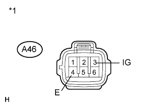
Text in Illustration *1 Front view of wire harness connector
(to Headlight Cleaner Control Relay)
Disconnect the A67 relay connector.
-
Measure the voltage according to the value(s) in the table below.
Standard Voltage Tester Connection Switch Condition Specified Condition A67-3 (IG) - Body ground Ignition switch ON 11 to 14 V A67-3 (IG) - Body ground Ignition switch off Below 1 V -
Measure the resistance according to the value(s) in the table below.
Standard Resistance Tester Connection Condition Specified Condition A67-4 (E) - Body ground Always Below 1 Ω
NG 
REPAIR OR REPLACE HARNESS OR CONNECTOR
OK 
PROCEED TO NEXT SUSPECTED AREA SHOWN IN PROBLEM SYMPTOMS TABLE Click here
-
-
CHECK HARNESS AND CONNECTOR (HEADLIGHT CLEANER MOTOR - BATTERY)
-
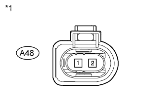
Text in Illustration *1 Front view of wire harness connector
(to Headlight Cleaner Motor and Pump Assembly)
Disconnect the A48 motor connector.
-
Measure the voltage according to the value(s) in the table below.
Standard Voltage Tester Connection Condition Specified Condition A48-1 - Body ground Always 11 to 14 V
NG
REPAIR OR REPLACE HARNESS OR CONNECTOR
OK
-
-
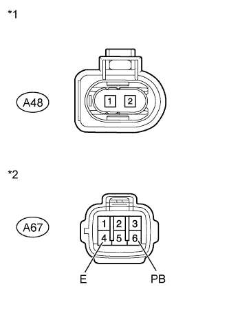
CHECK HARNESS AND CONNECTOR (HEADLIGHT CLEANER CONTROL RELAY - BATTERY AND BODY GROUND)
-
Text in Illustration *1 Front view of wire harness connector
(to Headlight Cleaner Control Relay)
Disconnect the A67 relay connector.
-
Measure the voltage according to the value(s) in the table below.
Standard Voltage Tester Connection Switch Condition Specified Condition A67-3 (IG) - Body ground Ignition switch ON 11 to 14 V A67-3 (IG) - Body ground Ignition switch off Below 1 V -
Measure the resistance according to the value(s) in the table below.
Standard Resistance Tester Connection Condition Specified Condition A67-4 (E) - Body ground Always Below 1 Ω
NG
REPAIR OR REPLACE HARNESS OR CONNECTOR
OK
-
-
INSPECT HEADLIGHT CLEANER MOTOR AND PUMP ASSEMBLY
-

Remove the headlight cleaner motor Click here.
-
Apply battery voltage to the headlight cleaner motor and check the operation of the headlight cleaner motor.
OK Measurement Condition Specified Condition Battery positive (+) → Terminal 1
Battery negative (-) → Terminal 2
Headlight cleaner motor operation is normal
NG
REPLACE HEADLIGHT CLEANER MOTOR AND PUMP ASSEMBLY Click here
OK
-
-
CHECK HARNESS AND CONNECTOR (HEADLIGHT CLEANER CONTROL RELAY - MAIN BODY ECU)
-
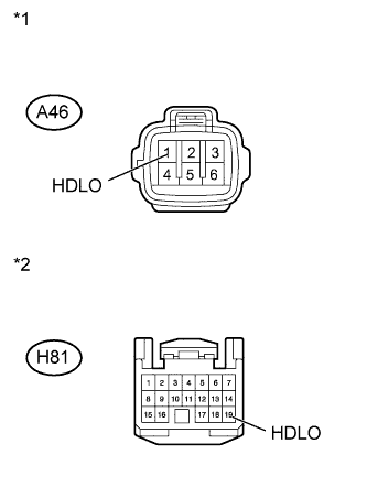
Text in Illustration *1 Front view of wire harness connector
(to Headlight Cleaner Control Relay)
*2 Front view of wire harness connector
(to Main Body ECU [Instrument Panel Junction Block Assembly])
Disconnect the A67 relay connector.
-
Disconnect the H81 ECU connector.
-
Measure the resistance according to the value(s) in the table below.
Standard Resistance Tester Connection Condition Specified Condition A67-1 (HDLO) - H81-19 (HDLO) Always Below 1 Ω A67-1 (HDLO) - Body ground Always 10 kΩ or higher
NG
REPAIR OR REPLACE HARNESS OR CONNECTOR
OK
-
-
CHECK HARNESS AND CONNECTOR (HEADLIGHT CLEANER MOTOR - HEADLIGHT CLEANER CONTROL RELAY)
-
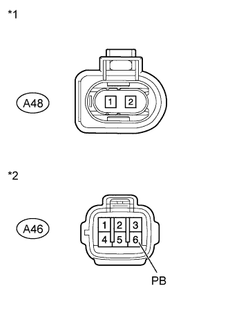
Text in Illustration *1 Front view of wire harness connector
(to Headlight Cleaner Motor and Pump Assembly)
*2 Front view of wire harness connector
(to Headlight Cleaner Control Relay)
Disconnect the A48 motor connector.
-
Disconnect the A67 relay connector.
-
Measure the resistance according to the value(s) in the table below.
Standard Resistance Tester Connection Condition Specified Condition A48-2 - A67-6 (PB) Always Below 1 Ω A67-6 (PB) - Body ground Always 10 kΩ or higher
NG
REPAIR OR REPLACE HARNESS OR CONNECTOR
OK
PROCEED TO NEXT SUSPECTED AREA SHOWN IN PROBLEM SYMPTOMS TABLE Click here
-
-
CHECK HARNESS AND CONNECTOR (HEADLIGHT CLEANER MOTOR - BATTERY)
-
Text in Illustration *1 Front view of wire harness connector
(to Headlight Cleaner Motor and Pump Assembly)
Disconnect the A48 motor connector.
-
Measure the voltage according to the value(s) in the table below.
Standard Voltage Tester Connection Condition Specified Condition A48-1 - Body ground Always 11 to 14 V
NG
REPAIR OR REPLACE HARNESS OR CONNECTOR
OK
-
-
CHECK HARNESS AND CONNECTOR (HEADLIGHT CLEANER CONTROL RELAY - BATTERY)
-
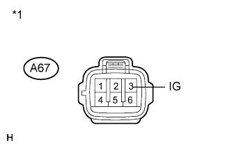
Text in Illustration *1 Front view of wire harness connector
(to Headlight Cleaner Control Relay)
Disconnect the A67 relay connector.
-
Measure the voltage according to the value(s) in the table below.
Standard Voltage Tester Connection Switch Condition Specified Condition A67-3 (IG) - Body ground Ignition switch ON 11 to 14 V A67-3 (IG) - Body ground Ignition switch off Below 1 V
NG
REPAIR OR REPLACE HARNESS OR CONNECTOR
OK
-
-
INSPECT HEADLIGHT CLEANER MOTOR AND PUMP ASSEMBLY
-
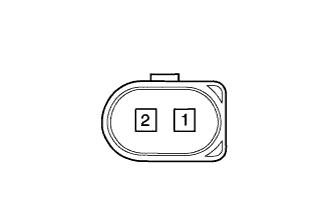
Remove the headlight cleaner motor Click here.
-
Apply battery voltage to the headlight cleaner motor and check the operation of the headlight cleaner motor.
OK Measurement Condition Specified Condition Battery positive (+) → Terminal 1
Battery negative (-) → Terminal 2
Headlight cleaner motor operation is normal
NG
REPLACE HEADLIGHT CLEANER MOTOR AND PUMP ASSEMBLY Click here
OK
-
-
CHECK HARNESS AND CONNECTOR (HEADLIGHT CLEANER MOTOR - HEADLIGHT CLEANER CONTROL RELAY AND BODY GROUND)
-
Text in Illustration *1 Front view of wire harness connector
(to Headlight Cleaner Motor and Pump Assembly)
*2 Front view of wire harness connector
(to Headlight Cleaner Control Relay)
Disconnect the A48 motor connector.
-
Disconnect the A67 relay connector.
-
Measure the resistance according to the value(s) in the table below.
Standard Resistance Tester Connection Condition Specified Condition A48-2 - A67-6 (PB) Always Below 1 Ω A67-4 (E) - Body ground Always Below 1 Ω A67-6 (PB) - Body ground Always 10 kΩ or higher
NG
REPAIR OR REPLACE HARNESS OR CONNECTOR
OK
PROCEED TO NEXT SUSPECTED AREA SHOWN IN PROBLEM SYMPTOMS TABLE Click here
-