WIPER AND WASHER SYSTEM (w/ Rain Sensor) Rain Sensor Circuit
DESCRIPTION
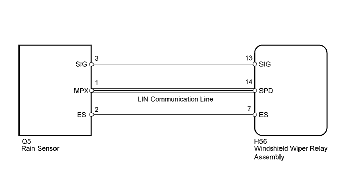
The windshield wiper relay assembly receives a signal from the rain sensor to control the auto wiper system.
WIRING DIAGRAM
INSPECTION PROCEDURE
PROCEDURE
-
CHECK COMMUNICATION FUNCTION OF LIN COMMUNICATION SYSTEM
-
Check that the LIN communication system is normal. Click here
OK LIN communication system is normal.
NG 
GO TO LIN COMMUNICATION SYSTEM Click here
OK 
-
-
CHECK HARNESS AND CONNECTOR (WINDSHIELD WIPER RELAY - RAIN SENSOR)
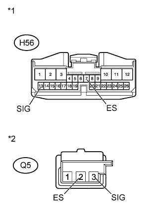
Text in Illustration *1 Front view of wire harness connector
(to Windshield Wiper Relay Assembly)
*2 Front view of wire harness connector
(to Rain Sensor)
-
Disconnect the H56 relay connector.
-
Disconnect the Q5 sensor connector.
-
Measure the resistance according to the value(s) in the table below.
Standard Resistance Tester Connection Condition Specified Condition H56-13 (SIG) - Q5-3 (SIG) Always Below 1 Ω Q5-3 (SIG) - Body ground Always 10 kΩ or higher H56-7 (ES) - Q5-2 (ES) Always Below 1 Ω Q5-2 (ES) - Body ground Always 10 kΩ or higher
NG
REPAIR OR REPLACE HARNESS OR CONNECTOR
OK
-
-
CHECK WINDSHIELD WIPER RELAY ASSEMBLY
-
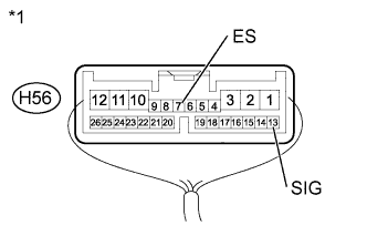
Text in Illustration *1 Component with harness connected
(Windshield Wiper Relay Assembly)
Remove the wiper relay with its connector still connected Click here for LHD, Click here for RHD).
-
Measure the voltage according to the value(s) in the table below.
Standard Voltage Tester Connection Switch Condition Specified Condition H56-13 (SIG) - H56-7 (ES) Ignition switch ON 11 to 14 V Result Result Proceed to OK A NG (for LHD) B NG (for RHD) C
B
REPLACE WINDSHIELD WIPER RELAY ASSEMBLY Click here
C
REPLACE WINDSHIELD WIPER RELAY ASSEMBLY Click here
A 
REPLACE RAIN SENSOR Click here
-