OUTER REAR VIEW MIRROR INSTALLATION

Tech Tips
-
Use the same procedure for RHD and LHD vehicles.
-
The procedure listed below is for LHD vehicles.
-
Use the same procedure for the RH and LH sides.
-
The procedure listed below is for the LH side.
-
A bolt without a torque specification is shown in the standard bolt chart Click here.
-
INSTALL OUTER REAR VIEW MIRROR ASSEMBLY LH
-
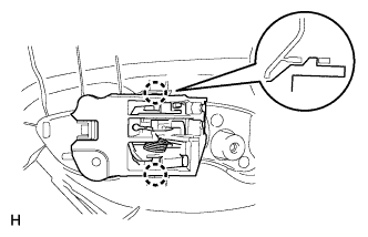
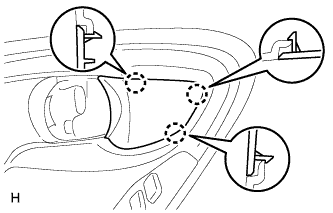
Attach the claw to install the outer rear view mirror assembly LH, and then install the 3 bolts.
- Torque:
- 5.5 N*m { 56 kgf*cm, 49 in.*lbf }
-
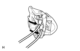
Attach the clamp.
-
Connect the connector.
-
-
INSTALL FRONT DOOR SERVICE HOLE COVER LH
-
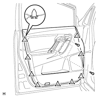
Apply butyl tape to the door.
-
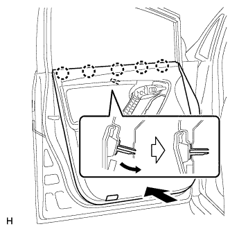
Pass the front door lock remote control cable and front door inside locking cable through a new front door service hole cover.
-
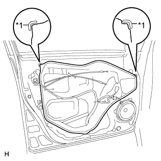
Text in Illustration *1 Reference Point Install the front door service hole cover according to the reference points on the front door panel.
Note
-
Securely install the front door service hole cover to prevent wrinkles and air bubbles.
-
There should be no wrinkles or folds after installing the service hole cover.
-
After installing the service hole cover, check the seal quality.
-
-
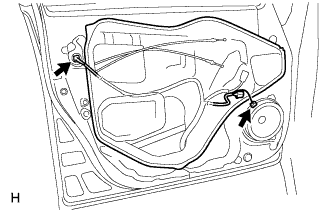
Connect the 2 connectors.
-
-
INSTALL OUTER MIRROR INSTALL HOLE COVER LH
-
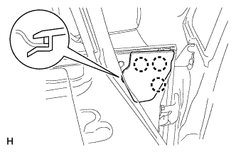
Attach the 3 claws to install the outer mirror install hole cover.
-
-
INSTALL FRONT DOOR INNER GLASS WEATHERSTRIP LH
-
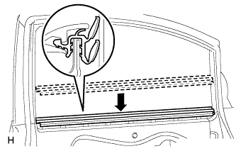
Install the front door inner glass weatherstrip.
-
-
INSTALL FRONT DOOR INSIDE HANDLE SUB-ASSEMBLY LH
-
Connect the front door lock remote control cable and front door inside locking cable to the front door inside handle sub-assembly to install the inside handle.
-
-
INSTALL FRONT DOOR TRIM BOARD SUB-ASSEMBLY LH
-
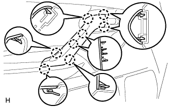
Attach the 2 claws to install the front door inside handle sub-assembly to the door trim board.
-
Attach the front door trim board with the 5 claws of the front door inner glass weatherstrip and the reference boss.
-
w/ Courtesy Light:
-
Connect the courtesy light connector.
-
-
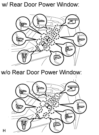
Attach the 9 clips to install the trim board.
-
Install the 3 screws.
-
-
INSTALL POWER WINDOW REGULATOR SWITCH ASSEMBLY WITH FRONT DOOR ARMREST BASE PANEL (for Front Passenger Side)
Tech Tips
Use the same procedure described for the driver side.
-
INSTALL POWER WINDOW REGULATOR MASTER SWITCH ASSEMBLY WITH FRONT DOOR ARMREST BASE PANEL (for Driver Side)
-
Connect the connector.
-
Attach the 7 claws and clip to install the power window regulator master switch assembly with front door armrest base panel.
-
-
INSTALL FRONT DOOR TRIM MOULDING LH
-
Attach the 8 claws to install the front door trim moulding.
-
-
INSTALL FRONT DOOR INSIDE HANDLE BEZEL LH
-
Attach the 3 claws to install the inside handle bezel.
-