ANTI-LOCK BRAKE SYSTEM, Diagnostic DTC:C1241/41

| DTC Code | DTC Name |
|---|---|
| C1241/41 | Low Battery Positive Voltage or Abnormally High Battery Positive Voltage |
DESCRIPTION
If a malfunction is detected in the power supply circuit, the skid control ECU (housed in the brake actuator assembly) stores this DTC and the fail-safe function prohibits ABS operation.
This DTC is stored when the IG1 terminal voltage deviates from the standard due to a malfunction in the power supply or charging circuit such as the battery, generator circuit, etc.
The DTC is cleared when the IG1 terminal voltage returns to normal (only when the voltage returns to normal from a voltage lower than the standard range).
| DTC Code | DTC Detection Condition | Trouble Area |
|---|---|---|
| C1241/41 | When the vehicle speed is more than 6 km/h (4 mph) and any of the following is detected:
|
|
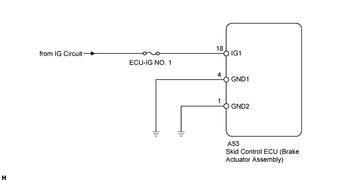
WIRING DIAGRAM
INSPECTION PROCEDURE
Note
Inspect the fuses for circuits related to this system before performing the following inspection procedure.
PROCEDURE
-
CHECK HARNESS AND CONNECTOR (IG1 TERMINAL)
-
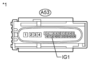
Text in Illustration *1 Front view of wire harness connector
(to Skid Control ECU)
Disconnect the skid control ECU connector.
-
Turn the ignition switch to ON.
-
Measure the voltage according to the value(s) in the table below.
Standard Voltage Tester Connection Switch Condition Specified Condition A53-18 (IG1) - Body ground Ignition switch ON 11 to 14 V
NG 
REPAIR OR REPLACE HARNESS OR CONNECTOR
OK 
-
-
CHECK HARNESS AND CONNECTOR (GND1, GND2 TERMINAL)
-
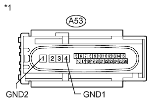
Text in Illustration *1 Front view of wire harness connector
(to Skid Control ECU)
Measure the resistance according to the value(s) in the table below.
Standard Resistance Tester Connection Condition Specified Condition A53-4 (GND1) - Body ground Always Below 1 Ω A53-1 (GND2) - Body ground Always Below 1 Ω
NG
REPAIR OR REPLACE HARNESS OR CONNECTOR
OK
-
-
RECONFIRM DTC
-
Reconnect the skid control ECU connector.
-
Clear the DTCs Click here.
-
Start the engine.
-
Perform a road test.
-
Check if the same DTC is output Click here.
Result Result Proceed to DTC C1241/41 is not output. A DTC C1241/41 is output. B
B
REPLACE BRAKE ACTUATOR ASSEMBLY Click here
A 
USE SIMULATION METHOD TO CHECK Click here
-