ANTI-LOCK BRAKE SYSTEM, Diagnostic DTC:C0210/33, C0215/34, C1273/73, C1274/74, C1332/38, C1333/39

| DTC Code | DTC Name |
|---|---|
| C0210/33 | Rear Speed Sensor RH Circuit |
| C0215/34 | Rear Speed Sensor LH Circuit |
| C1273/73 | Low Output Signal of Rear Speed Sensor RH (Test Mode DTC) |
| C1274/74 | Low Output Signal of Rear Speed Sensor LH (Test Mode DTC) |
| C1332/38 | Right Rear Speed Sensor Circuit |
| C1333/39 | Left Rear Speed Sensor Circuit |
DESCRIPTION
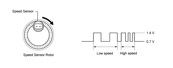
The speed sensor detects wheel speed and sends the appropriate signals to the skid control ECU. These signals are used for the anti-lock brake system.
Speed sensor rotors have rows of alternating N and S magnetic poles, and their magnetic fields change when the rotors turn.
Each speed sensor detects that magnetic field change and sends a pulse signal to the skid control ECU.
DTCs C1273/73 and C1274/74 are cleared when the speed sensor sends a vehicle speed signal or Test Mode ends. DTCs C1273/73 and C1274/74 are stored only in Test Mode.
| DTC Code | DTC Detection Condition | Trouble Area |
|---|---|---|
| C0210/33 C0215/34 |
When any of the following is detected:
|
|
| C1332/38 C1333/39 |
When either of the following is detected:
|
|
| C1273/73 C1274/74 |
Stored during Test Mode. |
|
Tech Tips
-
DTCs C0210/33, C1273/73 and C1332/38 are for the rear speed sensor RH.
-
DTCs C0215/34, C1274/74 and C1333/39 are for the rear speed sensor LH.
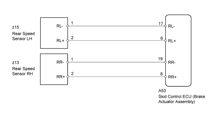
WIRING DIAGRAM
INSPECTION PROCEDURE
PROCEDURE
-
CHECK HARNESS AND CONNECTOR (MOMENTARY INTERRUPTION)
-
Using the intelligent tester, check for any momentary interruption in the wire harness and connector corresponding to the DTC Click here.
ABS/VSC/TRC Tester Display Measurement Item/Range Normal Condition Diagnostic Note RR Speed Open Rear speed sensor RH open detection / Error or Normal Normal - RL Speed Open Rear speed sensor LH open detection / Error or Normal Normal - Result Result Proceed to There are momentary interruptions. A There are no momentary interruptions. B There is a constant open circuit. C Tech Tips
Perform the above inspection before removing the sensor and connector.
B 
READ VALUE USING INTELLIGENT TESTER (RR/RL WHEEL SPEED) Click here
C
CHECK REAR SPEED SENSOR INSTALLATION Click here
A 
-
-
REPAIR OR REPLACE HARNESS OR CONNECTOR (SKID CONTROL ECU - REAR SPEED SENSOR)
-
Turn the ignition switch off.
-
Repair or replace the harness or connector.
-
Check that there is no momentary interruption between the skid control ECU and rear speed sensor Click here.
NEXT
-
-
RECONFIRM DTC
-
Turn the ignition switch off.
-
Clear the DTCs Click here.
-
Start the engine.
-
Drive the vehicle at a speed of 20 km/h (12 mph) or more for at least 30 seconds.
-
Check if the same DTC is output Click here.
Result Result Proceed to DTC C0210/33, C0215/34, C1332/38 and/or C1333/39 is output. A DTC C0210/33, C0215/34, C1332/38 and/or C1333/39 is not output. B
B 
END
A
-
-
READ VALUE USING INTELLIGENT TESTER (RR/RL WHEEL SPEED)
-
Turn the ignition switch off.
-
Connect the intelligent tester to the DLC3.
-
Start the engine.
-
Select the Data List mode on the intelligent tester Click here.
ABS/VSC/TRC Tester Display Measurement Item/Range Normal Condition Diagnostic Note RR Wheel Speed Rear speed sensor RH reading / min.: 0 km/h (0 mph), max.: 326 km/h (202 mph) Actual wheel speed Driving at constant speed: No large fluctuations RL Wheel Speed Rear speed sensor LH reading / min.: 0 km/h (0 mph), max.: 326 km/h (202 mph) Actual wheel speed Driving at constant speed: No large fluctuations -
Check that there is no significant difference between the speed value displayed on the intelligent tester and the speed value displayed on the speedometer when driving the vehicle.
Tech Tips
Factors that affect the indicated vehicle speed include tire size, tire inflation, and tire wear. The speed indicated on the speedometer has an allowable margin of error. This can be tested using a speedometer tester (calibrated chassis dynamometer). For details about testing and the margin of error, see the reference chart Click here.
OK The speed value displayed on the intelligent tester is the same or almost the same as the speed indicated on the speedometer.
NG
CHECK REAR SPEED SENSOR INSTALLATION Click here
OK
-
-
PERFORM TEST MODE (SIGNAL CHECK)
-
Perform the sensor check in the Test Mode procedure Click here.
OK No Test Mode DTCs are output.
NG
CHECK REAR SPEED SENSOR INSTALLATION Click here
OK
-
-
RECONFIRM DTC
-
Turn the ignition switch off.
-
Clear the DTCs Click here.
-
Start the engine.
-
Drive the vehicle at a speed of 20 km/h (12 mph) or more for at least 30 seconds.
-
Check if the same DTC is output Click here.
Result Result Proceed to DTC C0210/33, C0215/34, C1332/38 and/or C1333/39 is not output. A DTC C0210/33, C0215/34, C1332/38 and/or C1333/39 is output. B
B
REPLACE REAR SPEED SENSOR AND REAR SPEED SENSOR ROTOR Click here
A 
USE SIMULATION METHOD TO CHECK Click here
-
-
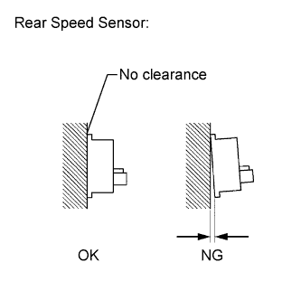
CHECK REAR SPEED SENSOR INSTALLATION
-
Turn the ignition switch off.
-
Check the speed sensor installation.
OK There is no clearance between the sensor and rear axle hub.
NG
REPLACE REAR AXLE HUB AND BEARING ASSEMBLY Click here
OK
-
-
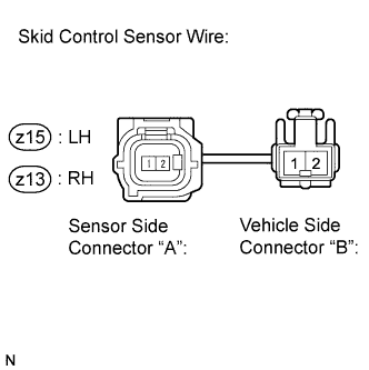
CHECK HARNESS AND CONNECTOR (SKID CONTROL SENSOR WIRE)
-
Remove the skid control sensor wire Click here.
-
Measure the resistance according to the value(s) in the table below.
Standard Resistance for RH Tester Connection Condition Specified Condition z13 ("A"-2) - z13 ("B"-1) Always Below 1 Ω z13 ("A"-2) - z13 ("B"-2) Always 10 kΩ or higher z13 ("A"-2) - Body ground Always 10 kΩ or higher z13 ("A"-1) - z13 ("B"-2) Always Below 1 Ω z13 ("A"-1) - z13 ("B"-1) Always 10 kΩ or higher z13 ("A"-1) - Body ground Always 10 kΩ or higher for LH Tester Connection Condition Specified Condition z15 ("A"-2) - z15 ("B"-1) Always Below 1 Ω z15 ("A"-2) - z15 ("B"-2) Always 10 kΩ or higher z15 ("A"-2) - Body ground Always 10 kΩ or higher z15 ("A"-1) - z15 ("B"-2) Always Below 1 Ω z15 ("A"-1) - z15 ("B"-1) Always 10 kΩ or higher z15 ("A"-1) - Body ground Always 10 kΩ or higher Note
Check the speed sensor signal after replacement Click here.
NG
REPLACE SKID CONTROL SENSOR WIRE Click here
OK
-
-
CHECK HARNESS AND CONNECTOR (SKID CONTROL ECU - REAR SPEED SENSOR)
-
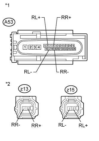
Text in Illustration *1 Front view of wire harness connector
(to Skid Control ECU)
*2 Front view of wire harness connector
(to Rear Speed Sensor)
Disconnect the skid control ECU connector.
-
Disconnect the rear speed sensor connector.
-
Measure the resistance according to the value(s) in the table below.
Standard Resistance for RH Tester Connection Condition Specified Condition A53-8 (RR+) - z13-2 (RR+) Always Below 1 Ω A53-8 (RR+) - Body ground Always 10 kΩ or higher A53-19 (RR-) - z13-1 (RR-) Always Below 1 Ω A53-19 (RR-) - Body ground Always 10 kΩ or higher for LH Tester Connection Condition Specified Condition A53-6 (RL+) - z15-2 (RL+) Always Below 1 Ω A53-6 (RL+) - Body ground Always 10 kΩ or higher A53-17 (RL-) - z15-1 (RL-) Always Below 1 Ω A53-17 (RL-) - Body ground Always 10 kΩ or higher
NG
REPAIR OR REPLACE HARNESS OR CONNECTOR
OK
-
-
INSPECT SKID CONTROL ECU (SENSOR INPUT)
-
Disconnect the rear speed sensor connector.
-
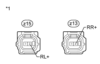
Text in Illustration *1 Front view of wire harness connector
(to Rear Speed Sensor)
Measure the voltage according to the value(s) in the table below.
Standard Voltage for RH Tester Connection Switch Condition Specified Condition z13-2 (RR+) - Body ground Ignition switch ON 8 to 14 V for LH Tester Connection Switch Condition Specified Condition z15-2 (RL+) - Body ground Ignition switch ON 8 to 14 V
NG
REPLACE BRAKE ACTUATOR ASSEMBLY Click here
OK
-
-
RECONFIRM DTC
-
Reconnect the skid control ECU connector and the rear speed sensor connector.
-
Clear the DTCs Click here.
-
Start the engine.
-
Drive the vehicle at a speed of 20 km/h (12 mph) or more for at least 30 seconds.
-
Check if the same DTC is output Click here.
Result Result Proceed to DTC C0210/33, C0215/34, C1332/38 and/or C1333/39 is output. A DTC C0210/33, C0215/34, C1332/38 and/or C1333/39 is not output. B
B
USE SIMULATION METHOD TO CHECK Click here
A
-
-
REPLACE REAR SPEED SENSOR AND REAR SPEED SENSOR ROTOR
-
Turn the ignition switch off.
-
Replace the rear axle hub and bearing assembly (rear speed sensor rotor) Click here.
Tech Tips
The rear speed sensor rotor is incorporated into the rear axle hub and bearing assembly.
If the rear speed sensor rotor needs to be replaced, replace it together with the rear axle hub and bearing assembly with rear speed sensor.
Note
Check the speed sensor signal after replacement Click here.
NEXT
-
-
RECONFIRM DTC
-
Clear the DTCs Click here.
-
Start the engine.
-
Drive the vehicle at a speed of 20 km/h (12 mph) or more for at least 30 seconds.
-
Check if the same DTC is output Click here.
Result Result Proceed to DTC C0210/33, C0215/34, C1332/38 and/or C1333/39 is not output. A DTC C0210/33, C0215/34, C1332/38 and/or C1333/39 is output. B
B
REPLACE BRAKE ACTUATOR ASSEMBLY Click here
A
END
-