FRONT SUSPENSION MEMBER INSTALLATION

-
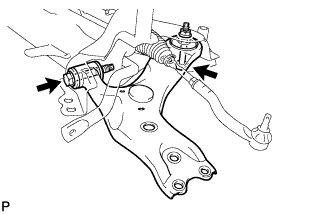
INSTALL STEERING GEAR ASSEMBLY
-
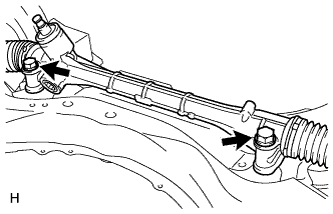
Install the steering gear to the front suspension crossmember with the 2 bolts and 2 nuts.
- Torque:
- 110 N*m { 1397 kgf*cm, 101 ft.*lbf }
Note
-
Make sure to tighten the bolts starting from the left side of the vehicle.
-
Because the nut has its own stopper, do not turn the nut. Tighten the bolt with the nut fixed in place.
-
-
INSTALL FRONT STABILIZER BAR
-
Install the front stabilizer bar to the front suspension crossmember so that the identification mark is positioned on the right side of the vehicle.
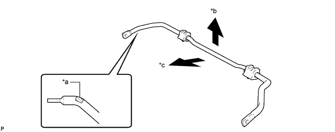
Text in Illustration *a Identification Mark *b Top of the Vehicle *c Front of the Vehicle - -
-
-
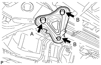
INSTALL FRONT SUSPENSION MEMBER FRONT BRACE LH
-
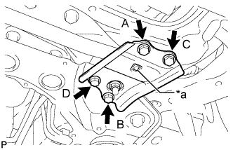
Text in Illustration *a Protrusion Install the front brace with the 4 bolts.
- Torque:
- 92 N*m { 938 kgf*cm, 68 ft.*lbf }
Note
-
Tighten the bolts in the order of B, C, D and A.
-
Make sure that the protrusion of the front stabilizer lower bracket bush protrudes from the hole of the front suspension member front brace LH when installing the front suspension member front brace LH.
-
-
INSTALL FRONT SUSPENSION MEMBER FRONT BRACE RH
-
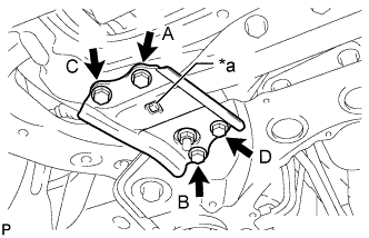
Text in Illustration *a Protrusion Install the front brace with the 4 bolts.
- Torque:
- 92 N*m { 938 kgf*cm, 68 ft.*lbf }
Note
-
Tighten the bolts in the order of B, C, D and A.
-
Make sure that the protrusion of the front stabilizer lower bracket bush protrudes from the hole of the front suspension member front brace RH when installing the front suspension member front brace RH.
-
-
TEMPORARILY INSTALL FRONT NO. 1 LOWER SUSPENSION ARM SUB-ASSEMBLY LH
-
Position the front suspension crossmember on a level surface.
-
Temporarily install the front lower suspension arm LH to the front suspension crossmember with the 2 bolts and nut.
Note
Because the nut has its own stopper, do not turn the nut. Tighten the bolt with the nut fixed in place.
-
-
TEMPORARILY INSTALL FRONT NO. 1 LOWER SUSPENSION ARM SUB-ASSEMBLY RH
Tech Tips
Perform the same procedure as for the LH side.
-
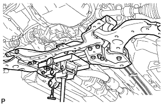
INSTALL FRONT SUSPENSION CROSSMEMBER SUB-ASSEMBLY
-
Support the front suspension crossmember with a transmission jack.
-
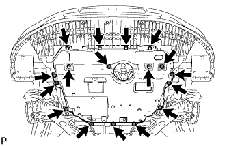
Install the front suspension crossmember with the 4 bolts and 2 nuts, and tighten the bolts and nuts in several steps while alternately inserting SST into the left and right reference holes of the front suspension crossmember.
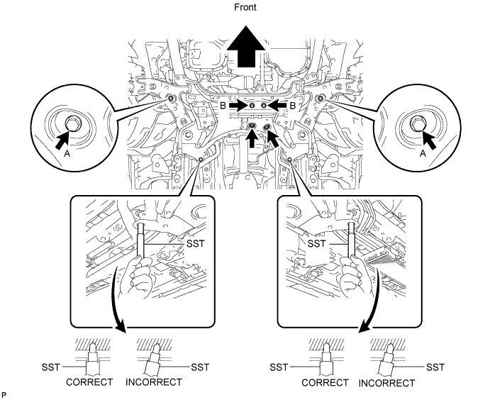
- SST
- 09670-00020
- Torque:
- for bolt A
- 137 N*m { 1397 kgf*cm, 101 ft.*lbf }
- for bolt B
- 95 N*m { 969 kgf*cm, 70 ft.*lbf }
- for nut
- 95 N*m { 969 kgf*cm, 70 ft.*lbf }
-
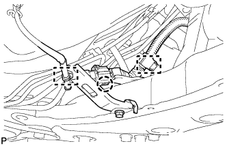
Attach the 2 clamps and claw to connect the oxygen sensor wire to the front suspension crossmember.
-
-
INSTALL FRONT SUSPENSION MEMBER REAR BRACE LH
-
Install the rear brace with the 3 bolts.
- Torque:
- for bolt A
- 137 N*m { 1397 kgf*cm, 101 ft.*lbf }
- for bolt B
- 93 N*m { 948 kgf*cm, 69 ft.*lbf }
-
-
INSTALL FRONT SUSPENSION MEMBER REAR BRACE RH
Tech Tips
Perform the same procedure as for the LH side.
-
INSTALL REAR SIDE RAIL REINFORCEMENT SUB-ASSEMBLY LH
-
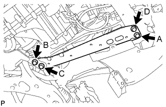
Install the reinforcement with the 4 bolts.
- Torque:
- 99 N*m { 1010 kgf*cm, 73 ft.*lbf }
Note
Tighten the bolts in the order of C, B, D and A.
-
-
INSTALL REAR SIDE RAIL REINFORCEMENT SUB-ASSEMBLY RH
-
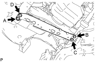
Install the reinforcement with the 4 bolts.
- Torque:
- 99 N*m { 1010 kgf*cm, 73 ft.*lbf }
Note
Tighten the bolts in the order of C, B, D and A.
-
-
INSTALL FRONT LOWER ENGINE MOUNTING BRACKET REINFORCEMENT
-
Install the front lower engine mounting bracket reinforcement with the 2 bolts.
- Torque:
- 99 N*m { 1010 kgf*cm, 73 ft.*lbf }
-
-
CONNECT FRONT NO. 1 LOWER SUSPENSION ARM SUB-ASSEMBLY LH
-
Connect the suspension lower arm to the lower ball joint with the bolt and 2 nuts.
- Torque:
- 89 N*m { 908 kgf*cm, 66 ft.*lbf }
Note
Do not angle past full bound or full rebound when bushing is tightened.
-
-
CONNECT FRONT NO. 1 LOWER SUSPENSION ARM SUB-ASSEMBLY RH
Tech Tips
Perform the same procedure as for the LH side.
-
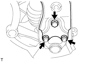
CONNECT TIE ROD END SUB-ASSEMBLY LH
-
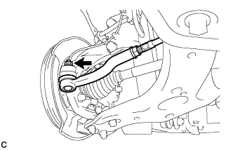
Connect the tie rod end to the steering knuckle with the nut.
- Torque:
- 49 N*m { 500 kgf*cm, 36 ft.*lbf }
Note
Tighten the nut up to an additional 60° if the holes for the cotter pin are not aligned.
-
Install a new cotter pin.
-
-
CONNECT TIE ROD END SUB-ASSEMBLY RH
Tech Tips
Perform the same procedure as for the LH side.
-
CONNECT FRONT STABILIZER LINK ASSEMBLY LH
-
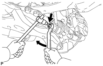
Connect the front stabilizer link to the front stabilizer bar with the nut.
- Torque:
- 74 N*m { 755 kgf*cm, 55 ft.*lbf }
Tech Tips
If the ball joint turns together with the nut, use a 6 mm hexagon wrench to hold the stud bolt.
-
-
CONNECT FRONT STABILIZER LINK ASSEMBLY RH
Tech Tips
Perform the same procedure as for the LH side.
-
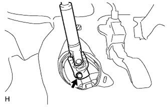
INSTALL NO. 1 STEERING COLUMN HOLE COVER SUB-ASSEMBLY
-
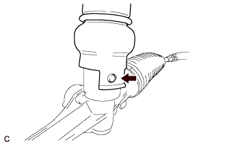
Align the round hole in the No. 1 steering column hole cover with the protrusion of the steering gear and install the cover.
-
-
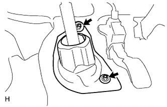
CONNECT NO. 2 STEERING INTERMEDIATE SHAFT ASSEMBLY
-
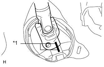
Text in Illustration *1 Matchmark Align the matchmarks on the No. 2 steering intermediate shaft assembly and steering intermediate shaft assembly.
-
Install the bolt.
- Torque:
- 35 N*m { 360 kgf*cm, 26 ft.*lbf }
-
-
INSTALL COLUMN HOLE COVER SILENCER SHEET
-
Install the column hole cover silencer sheet with the 2 clips.
-
Install the floor carpet.
-
-
INSTALL NO. 2 ENGINE UNDER COVER
-
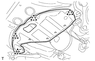
Install the under cover with the 4 clips.
-
-
INSTALL REAR ENGINE UNDER COVER LH
-
Install the under cover with the 5 clips.
-
-
INSTALL REAR ENGINE UNDER COVER RH
Tech Tips
Perform the same procedure as for the LH side.
-
INSTALL FRONT WHEELS
- Torque:
- 103 N*m { 1050 kgf*cm, 76 ft.*lbf }
-
STABILIZE SUSPENSION
-
Lower the vehicle.
-
Bounce the vehicle up and down at the corners several times to stabilize the suspension.
-
-
INSTALL CENTER NO. 4 ENGINE UNDER COVER
-
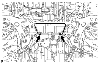
Install the under cover with the 2 clips.
-
-
INSTALL NO. 1 ENGINE UNDER COVER (for 1ZR-FAE, 2ZR-FAE)
-
Install the under cover with the 11 clips and 6 bolts.
-
-
INSTALL NO. 1 ENGINE UNDER COVER (for 1AD-FTV, 2AD-FHV)
-
Install the No. 1 engine under cover with the 10 clips and 6 bolts.
-
-
INSTALL NO. 1 ENGINE UNDER COVER (for 1WW)
-
Install the No. 1 engine under cover with the 11 clips and 6 bolts.
-
-
TIGHTEN FRONT NO. 1 LOWER SUSPENSION ARM SUB-ASSEMBLY LH
-
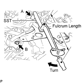
Using SST, tighten bolt A.
- SST
- 09961-01270
- Torque:
- without SST
- 233 N*m { 2376 kgf*cm, 172 ft.*lbf }
- with SST
- 172 N*m { 1755 kgf*cm, 127 ft.*lbf }
Note
-
Because the nut has its own stopper, do not turn the nut. Tighten the bolt with the nut fixed in place.
-
Use a torque wrench with a fulcrum length of 425 mm (1.39 ft.).
-
This torque value is effective when SST is parallel to the torque wrench.
-
The final torque must be applied under standard vehicle height conditions.
-
Tighten bolt B.
- Torque:
- 214 N*m { 2182 kgf*cm, 158 ft.*lbf }
-
-
TIGHTEN FRONT NO. 1 LOWER SUSPENSION ARM SUB-ASSEMBLY RH
Tech Tips
Perform the same procedure as for the LH side.
-
INSPECT AND ADJUST FRONT WHEEL ALIGNMENT
-
Inspect and adjust the front wheel alignment Click here.
-
-
ADJUST HEADLIGHT ASSEMBLY
-
for Halogen Headlight:
Adjust the headlight assembly Click here.
-
for HID Headlight:
Adjust the headlight assembly Click here.
-