- Click here
PLACE FRONT WHEELS FACING STRAIGHT AHEAD
- Click here
REMOVE FRONT WHEELS
- Click here
REMOVE NO. 1 ENGINE UNDER COVER (for 1ZR-FAE, 2ZR-FAE)
-
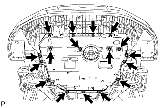
Remove the 11 clips, 6 bolts and under cover.
-
- Click here
REMOVE NO. 1 ENGINE UNDER COVER (for 1AD-FTV, 2AD-FHV)
-
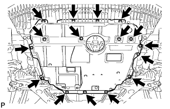
Remove the 6 bolts and 10 clips.
-
Remove the No. 1 engine under cover.
-
- Click here
REMOVE CENTER NO. 4 ENGINE UNDER COVER
-
Remove the 2 clips and under cover.
-
- Click here
REMOVE REAR ENGINE UNDER COVER LH
-
Remove the 5 clips and under cover.
-
- Click here
REMOVE REAR ENGINE UNDER COVER RH
Tip:Perform the same procedure as for the LH side.
- Click here
REMOVE NO. 2 ENGINE UNDER COVER
-
Remove the 4 clips and No. 2 engine under cover.
-
- Click here
SECURE STEERING WHEEL
- Click here
REMOVE COLUMN HOLE COVER SILENCER SHEET
-
Fold back the floor carpet, and then remove the 2 clips and then column hole cover silencer sheet.
-
- Click here
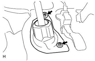
DISCONNECT NO. 2 STEERING INTERMEDIATE SHAFT ASSEMBLY
-
Remove the bolt.
Note:Do not disconnect the No. 2 steering intermediate shaft assembly from the steering intermediate shaft.
-
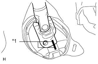
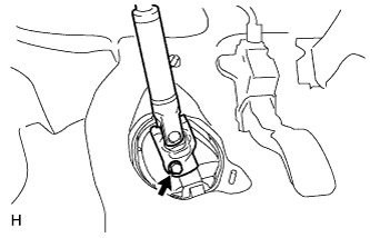
Put matchmarks on the No. 2 steering intermediate shaft assembly and steering intermediate shaft.
Table 1. Text in Illustration *1 Matchmark -
Disconnect the No. 2 steering intermediate shaft assembly from the steering intermediate shaft.
-
- Click here
REMOVE NO. 1 STEERING COLUMN HOLE COVER SUB-ASSEMBLY
-
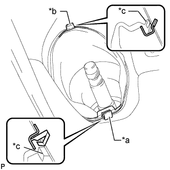
Remove clip A and the No. 1 steering column hole cover and detach clip B from the body.
Table 2. Text in Illustration *a Clip A *b Clip B *c Lip Note:Do not damage clip A or B.
-
-
Click here
DISCONNECT FRONT STABILIZER LINK ASSEMBLY LH
-
Remove the nut and disconnect the stabilizer link assembly LH from the front stabilizer bar.
Tip:If the ball joint turns together with the nut, use a 6 mm hexagon wrench to hold the stud bolt.
-
- Click here
DISCONNECT FRONT STABILIZER LINK ASSEMBLY RH
Tip:Perform the same procedure as for the LH side.
- Click here
DISCONNECT TIE ROD END SUB-ASSEMBLY LH
-
Remove the cotter pin and nut.
-
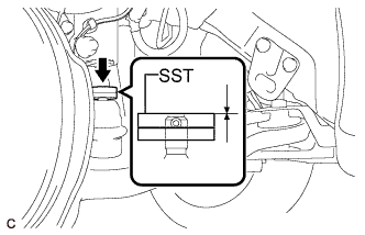
Install SST to the tie rod end.
09960-20010 09961-02060 Note:Make sure that the top of SST aligns with the top of the tie rod end.
-
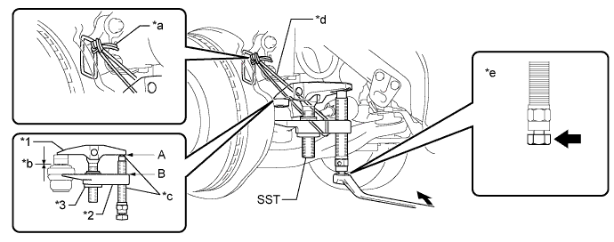
Using SST, separate the tie rod end from the steering knuckle.
09960-20010 09961-02010 Table 3. Text in Illustration *1 Body *2 Claw *3 Nut *4 Spacer B *a Tie the string without allowing slack *b 1 mm (0.0397 in.) *c Molybdenum Grease Application Area *d String *e Place the wrench here - - CAUTION:Apply grease to the bolt threads and the tip of SST.
Note:
-
Be sure to tighten the string firmly to secure SST to the steering knuckle to prevent SST from falling off.
-
Install SST with the center nut so that A and B are parallel. Otherwise, the dust cover may be damaged.
-
Be sure to place the wrench on the part indicated in the illustration.
-
Do not damage the front disc brake dust cover.
-
Do not damage the ball joint dust cover.
-
Do not damage the steering knuckle.
-
-
- Click here
DISCONNECT TIE ROD END SUB-ASSEMBLY RH
Tip:Perform the same procedure as for the LH side.
- Click here
LOOSEN FRONT NO. 1 LOWER SUSPENSION ARM SUB-ASSEMBLY LH
-
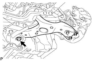
Loosen the bolt.
Note:Because the nut has its own stopper, do not turn the nut. Loosen the bolt with the nut fixed in place.
-
- Click here
DISCONNECT FRONT NO. 1 LOWER SUSPENSION ARM SUB-ASSEMBLY LH
-
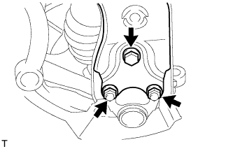
Remove the bolt and 2 nuts.
-
Disconnect the front suspension lower arm from the lower ball joint.
-
- Click here
DISCONNECT FRONT NO. 1 LOWER SUSPENSION ARM SUB-ASSEMBLY RH
Tip:Perform the same procedure as for the LH side.
- Click here
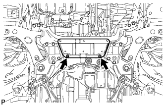
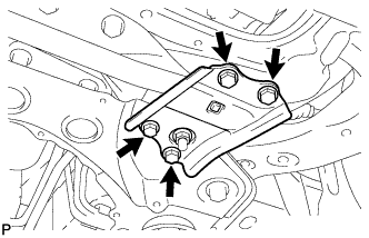
REMOVE FRONT LOWER ENGINE MOUNTING BRACKET REINFORCEMENT
-
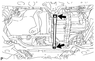
Remove the 2 bolts and front lower engine mounting bracket reinforcement.
-
- Click here
REMOVE REAR SIDE RAIL REINFORCEMENT SUB-ASSEMBLY LH
-
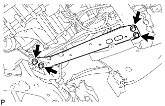
Remove the 4 bolts and front suspension member reinforcement LH.
-
- Click here
REMOVE REAR SIDE RAIL REINFORCEMENT SUB-ASSEMBLY RH
-
Remove the 4 bolts and front suspension member reinforcement RH.
-
- Click here
REMOVE FRONT SUSPENSION MEMBER REAR BRACE LH
-
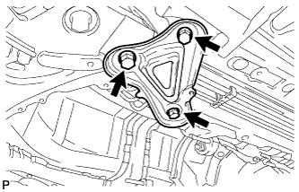
Remove the 3 bolts and front suspension member rear brace LH.
-
- Click here
REMOVE FRONT SUSPENSION MEMBER REAR BRACE RH
Tip:Perform the same procedure as for the LH side.
- Click here
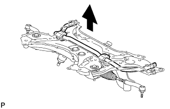
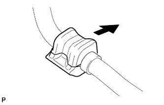
REMOVE FRONT SUSPENSION CROSSMEMBER SUB-ASSEMBLY
-
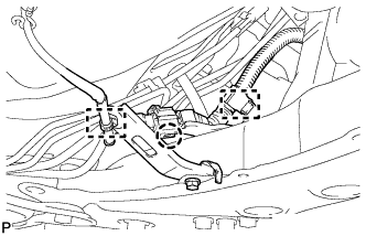
Detach the 2 clamps and claw, and disconnect the oxygen sensor wire from the front suspension crossmember.
-
Support the front suspension crossmember with a transmission jack.
-
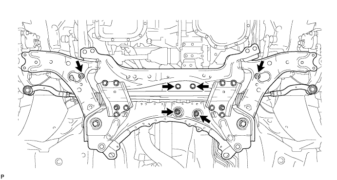
Remove the 4 bolts, 2 nuts and front suspension crossmember.
-
- Click here
REMOVE FRONT NO. 1 LOWER SUSPENSION ARM SUB-ASSEMBLY LH
-
Remove the 2 bolts, nut and front lower suspension arm from the front suspension crossmember.
Note:Because the nut has its own stopper, do not turn the nut. Loosen the bolt with the nut fixed in place.
-
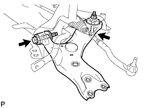
- Click here
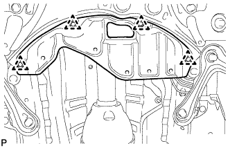
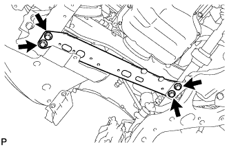
REMOVE FRONT SUSPENSION MEMBER FRONT BRACE LH
-
Remove the 4 bolts and front suspension member front brace.
-
- Click here
REMOVE FRONT SUSPENSION MEMBER FRONT BRACE RH
Tip:Perform the same procedure as for the LH side.
- Click here
REMOVE FRONT STABILIZER BAR
-
Remove the front stabilizer bar from the front suspension crossmember.
-
- Click here
REMOVE FRONT STABILIZER LOWER BRACKET BUSH LH
-
Remove the 2 bushes from the front stabilizer bar.
-
- Click here
REMOVE FRONT STABILIZER LOWER BRACKET BUSH RH
Tip:Perform the same procedure as for the LH side.