FRONT LOWER BALL JOINT INSTALLATION

Tech Tips
-
Use the same procedure for the RH and LH sides.
-
The procedure listed below is for the LH side.
-
INSTALL FRONT LOWER BALL JOINT ASSEMBLY LH
-
Secure the front axle assembly between aluminum plates in a vise.
Note
When using a vise, do not overtighten it.
-
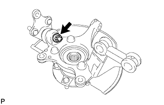
Install the front lower ball joint to the front axle assembly with the nut.
- Torque:
- 133 N*m { 1356 kgf*cm, 98 ft.*lbf }
-
Install a new cotter pin.
Note
If the holes for the cotter pin are not aligned, align the holes by tightening the nut as necessary up to an additional 60°.
-
-
INSTALL FRONT AXLE ASSEMBLY LH
-
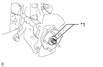
Text in Illustration *1 Matchmark Align the matchmarks and install the front drive shaft assembly to the front axle hub sub-assembly.
-
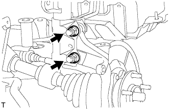
Install the front axle assembly to the front shock absorber assembly with coil spring with the 2 bolts and 2 nuts.
- Torque:
- 240 N*m { 2447 kgf*cm, 177 ft.*lbf }
Note
Be careful not to damage the drive shaft boot or the magnet rotor of the hub and bearing.
-
-
CONNECT FRONT NO. 1 LOWER SUSPENSION ARM SUB-ASSEMBLY LH
-
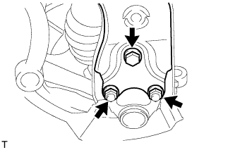
Connect the suspension lower arm to the lower ball joint with the bolt and 2 nuts.
- Torque:
- 89 N*m { 908 kgf*cm, 66 ft.*lbf }
Note
Do not angle past full bound or full rebound when bushing is tightened.
-
-
CONNECT TIE ROD END SUB-ASSEMBLY LH
-
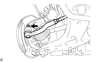
Connect the tie rod end to the steering knuckle with the nut.
- Torque:
- 49 N*m { 500 kgf*cm, 36 ft.*lbf }
Note
Tighten the nut up to an additional 60° if the holes for the cotter pin are not aligned.
-
Install a new cotter pin.
-
-
INSTALL FRONT DISC
-
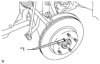
Text in Illustration *1 Matchmark Align the matchmarks of the disc and axle hub and install the disc.
-
-
CONNECT FRONT DISC BRAKE CALIPER ASSEMBLY LH
-
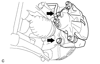
Install the front disc brake cylinder assembly to the steering knuckle with the 2 bolts.
- Torque:
- 107 N*m { 1089 kgf*cm, 79 ft.*lbf }
-
-
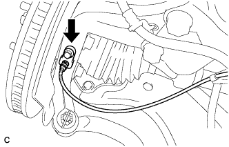
CONNECT FRONT FLEXIBLE HOSE
-
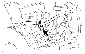
Connect the front flexible hose to the steering knuckle with the bolt.
- Torque:
- 29 N*m { 296 kgf*cm, 21 ft.*lbf }
-
-
CONNECT FRONT SPEED SENSOR LH
-
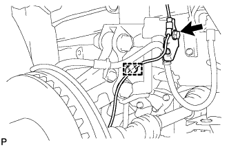
Install the front speed sensor wire and front flexible hose to the front shock absorber with the bolt, and attach the clamp.
- Torque:
- 29 N*m { 296 kgf*cm, 21 ft.*lbf }
Tech Tips
Install the front flexible hose first and then the speed sensor wire bracket.
Note
Do not twist the front speed sensor wire when installing it.
-
Install the front speed sensor to the steering knuckle with the bolt.
- Torque:
- 8.5 N*m { 87 kgf*cm, 75 in.*lbf }
Note
Do not twist the front speed sensor wire when installing the front speed sensor
-
-
INSTALL FRONT AXLE SHAFT NUT LH
-
Clean the threaded parts on the drive shaft and a new axle shaft nut using a non-residue solvent.
Note
-
Be sure to perform this work for a new drive shaft.
-
Keep the threaded parts free of oil and foreign objects.
-
-
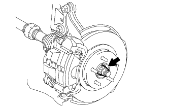
Using a 30 mm socket wrench, temporarily install the axle shaft nut.
- Torque:
- for Gasoline Engine
- 216 N*m { 2203 kgf*cm, 159 ft.*lbf }
- for Diesel Engine
- 292 N*m { 2978 kgf*cm, 215 ft.*lbf }
Tech Tips
Stake the nut after inspecting for looseness and runout in the following steps.
-
-
INSTALL FRONT WHEEL
- Torque:
- 103 N*m { 1050 kgf*cm, 76 ft.*lbf }
-
INSPECT AND ADJUST FRONT WHEEL ALIGNMENT
-
Inspect and adjust the front wheel alignment Click here.
-
-
CHECK SPEED SENSOR SIGNAL
-
w/o VSC:
Check the speed sensor signal Click here.
-
w/ VSC:
Check the speed sensor signal Click here.
-
-
ADJUST HEADLIGHT ASSEMBLY
-
for Halogen Headlight:
Adjust the headlight assembly Click here.
-
for HID Headlight:
Adjust the headlight assembly Click here.
-