REAR AXLE BEAM REMOVAL

-
REMOVE PARKING BRAKE ASSEMBLY
-
Remove the parking brake assembly Click here.
-
-
REMOVE REAR FLOOR SIDE MEMBER COVER LH
-
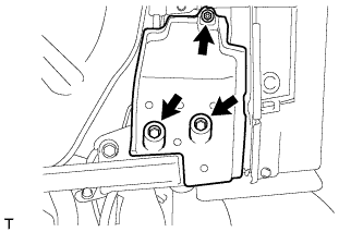
Remove the nut, 2 bolts and rear floor side member cover LH.
-
-
REMOVE REAR FLOOR SIDE MEMBER COVER RH
-
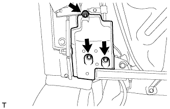
Remove the nut, 2 bolts and rear floor side member cover RH.
-
-
REMOVE REAR FLOOR SIDE MEMBER BRACE SUB-ASSEMBLY
-
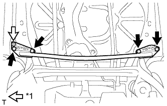
Text in Illustration *1 Clip Remove the 4 bolts, detach the clip and remove the rear floor side member brace.
-
-
REMOVE REAR HEIGHT CONTROL SENSOR SUB-ASSEMBLY RH (w/ HID Headlight)
-
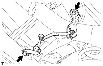
Remove the 2 bolts and rear height control sensor.
-
Disconnect the connector.
-
-
DISCONNECT SKID CONTROL SENSOR WIRE (for LH Side)
-
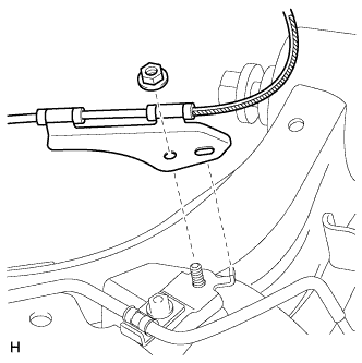
Remove the nut and sensor clamp.
-
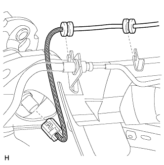
Detach the 2 grommets.
-
Disconnect the skid control sensor wire connector from the skid control sensor.
-
-
DISCONNECT SKID CONTROL SENSOR WIRE (for RH Side)
Tech Tips
Perform the same procedure as for the LH side.
-
DRAIN BRAKE FLUID
Note
Immediately wash off any brake fluid that comes into contact with any painted surfaces.
-
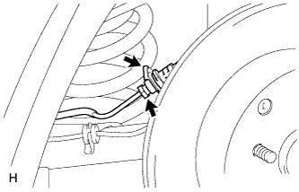
DISCONNECT REAR FLEXIBLE HOSE LH
-
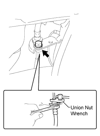
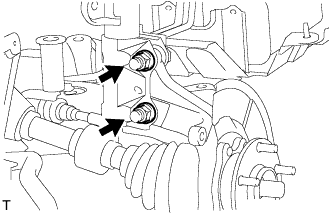
Using a union nut wrench, disconnect the brake tube while holding the rear flexible hose LH with a wrench.
Note
-
Do not bend or damage the brake tube.
-
Do not allow any foreign matter such as dirt or dust to enter the brake tube from the connection points.
-
-
Remove the bolt and disconnect the rear flexible hose LH.
-
-
DISCONNECT REAR FLEXIBLE HOSE RH
-
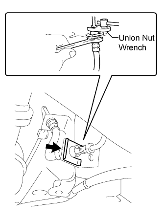
Using a union nut wrench, disconnect the brake tube while holding the rear flexible hose RH with a wrench.
Note
-
Do not bend or damage the brake tube.
-
Do not allow any foreign matter such as dirt or dust to enter the brake tube from the connection points.
-
-
Remove the clip and disconnect the rear flexible hose RH.
-
-
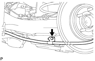
DISCONNECT REAR BRAKE FLEXIBLE HOSE (for LH Side)
-
Using a union nut wrench, disconnect the brake tube while holding the rear brake flexible hose with a wrench.
Note
-
Do not bend or damage the brake tube.
-
Do not allow any foreign matter such as dirt or dust to enter the brake tube from the connection points.
-
-
Remove the clip and disconnect the rear brake flexible hose.
-
-
DISCONNECT REAR BRAKE FLEXIBLE HOSE (for RH Side)
Tech Tips
Perform the same procedure as for the LH side.
-
REMOVE NO. 4 REAR BRAKE TUBE
-
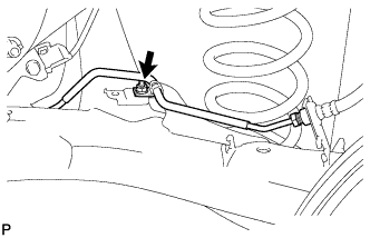
Remove the nut and No. 4 rear brake tube from the rear axle beam assembly.
-
-
REMOVE NO. 3 REAR BRAKE TUBE
Tech Tips
Perform the same procedure as for the No. 4 rear brake tube.
-
DISCONNECT NO. 3 PARKING BRAKE CABLE ASSEMBLY
-
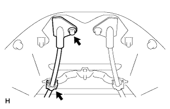
Remove the bolt and casing cap from the body.
-
Detach the clamp.
-
Remove the bolt and disconnect the parking brake cable.
-
-
DISCONNECT NO. 2 PARKING BRAKE CABLE ASSEMBLY
Tech Tips
Perform the same procedure as for the No. 3 parking brake cable assembly.
-
REMOVE REAR AXLE HUB AND BEARING ASSEMBLY LH
-
Remove the 2 bolts and 2 nuts, and disconnect the front shock absorber assembly with coil spring from the steering knuckle.
Tech Tips
While holding the nuts in place, loosen and remove the bolts.
-
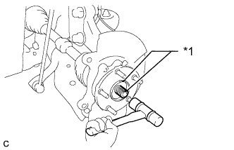
Text in Illustration *1 Matchmark Put matchmarks on the drive shaft and front axle hub sub-assembly.
-
Using a plastic-faced hammer, remove the front axle assembly.
Note
Be careful not to damage the front axle outboard joint boot or the magnet rotor of the hub and bearing. Do not push out the drive shaft from the axle assembly with excessive force.
-
-
REMOVE REAR DISC BRAKE DUST COVER SUB-ASSEMBLY LH
-
REMOVE REAR AXLE HUB AND BEARING ASSEMBLY RH
Tech Tips
Perform the same procedure as for the LH side.
-
REMOVE REAR DISC BRAKE DUST COVER SUB-ASSEMBLY RH
-
LOOSEN REAR AXLE BEAM ASSEMBLY
-
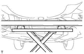
Support the rear axle beam assembly using an engine lift and 2 wooden blocks as shown in the illustration.
Tech Tips
Support the rear shock absorber assembly LH at a position where it compresses by approximately 20 to 30 mm (0.787 to 1.18 in.).
-
Loosen the 2 bolts of the rear axle beam assembly.
Note
Do not remove the bolts.
-
-
DISCONNECT REAR SHOCK ABSORBER ASSEMBLY LH
-
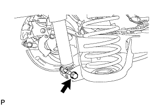
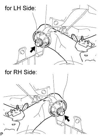
Remove the bolt while holding the nut and disconnect the rear shock absorber LH.
Note
Do not turn the nut.
-
-
DISCONNECT REAR SHOCK ABSORBER ASSEMBLY RH
Tech Tips
Perform the same procedure as for the LH side.
-
REMOVE REAR COIL SPRING LH
-
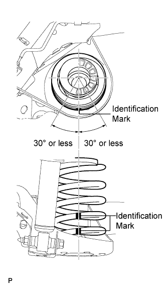
Slowly lower the engine lift and remove the rear coil spring.
Note
-
When reusing the rear coil spring, make sure that the identification marks are at the position shown in the illustration.
-
If the identification marks have come off, apply new paint at the positions shown in the illustration.
-
When moving the rear axle beam assembly beyond full rebound, make sure that the beam is not out of position for more than 10 minutes.
-
-
-
REMOVE REAR COIL SPRING UPPER INSULATOR LH
-
REMOVE REAR COIL SPRING LOWER INSULATOR LH
-
REMOVE REAR COIL SPRING RH
Tech Tips
Perform the same procedure as for the LH side.
-
REMOVE REAR COIL SPRING UPPER INSULATOR RH
-
REMOVE REAR COIL SPRING LOWER INSULATOR RH
-
REMOVE REAR AXLE BEAM ASSEMBLY
-
Remove the 2 bolts and the rear axle beam assembly.
-
-
REMOVE REAR AXLE CARRIER BUSHING LH
-
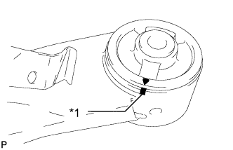
Text in Illustration *1 Matchmark Put a matchmark on the rear axle beam assembly so that the mark aligns with the arrow mark on the rear axle carrier bushing LH.
-
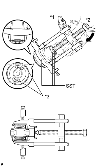
Text in Illustration *1 Hold *2 Turn *3 Rib Using a chisel and hammer, bend the 2 ribs on the bushing.
Note
When removing the bushing, do not erase the matchmark on the rear axle beam assembly.
-
Using SST, remove the bushing LH from the rear axle beam assembly.
- SST
- 09950-40011 ( 09951-04020, 09952-04010, 09953-04030, 09954-04020, 09955-04051, 09957-04010, 09958-04011 )
- 09710-26011 ( 09710-05061 )
- 09950-60010 ( 09951-00530 )
-
-
REMOVE REAR AXLE CARRIER BUSHING RH
Tech Tips
Perform the same procedure as for the LH side.