REAR AXLE BEAM INSTALLATION

-
INSTALL REAR AXLE CARRIER BUSHING LH
-
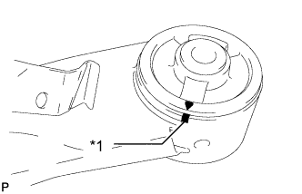
Text in Illustration *1 Matchmark Align the arrow mark on a new rear axle carrier bushing LH with the matchmark on the rear axle beam assembly and temporarily install the rear axle carrier bushing LH to the rear axle beam assembly.
Note
Be sure to install the bushing in the correct direction.
-
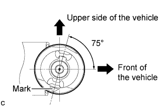
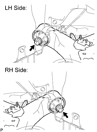
Turn the rear axle carrier bushing LH so that its position is as shown in the illustration.
-
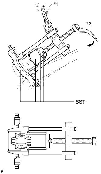
Text in Illustration *1 Hold *2 Turn Using SST, press the bushing LH into the rear axle beam assembly.
- SST
- 09710-04101
- 09950-40011 ( 09951-04020, 09952-04010, 09953-04030, 09954-04020, 09955-04051, 09957-04010, 09958-04011 )
- 09950-60010 ( 09951-00620 )
Note
Do not damage the rubber portion when installing the bushing.
-
-
INSTALL REAR AXLE CARRIER BUSHING RH
Tech Tips
Perform the same procedure as for the LH side.
-
TEMPORARILY INSTALL REAR AXLE BEAM ASSEMBLY
-
Temporarily install the rear axle beam assembly with the 2 bolts.
-
-
INSTALL REAR COIL SPRING UPPER INSULATOR LH
-
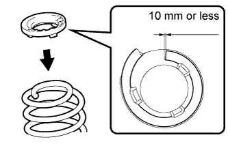
Install the rear coil spring upper insulator to the rear coil spring.
Note
Install the rear coil spring upper insulator so that the distance between the stopper and the upper end of the rear coil spring is 10 mm (0.393 in.) or less.
-
-
INSTALL REAR COIL SPRING LOWER INSULATOR LH
-
INSTALL REAR COIL SPRING LH
-
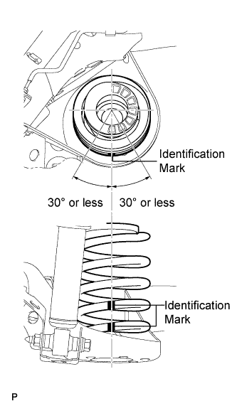
Install the rear coil spring to the rear axle beam.
Note
Install the rear coil spring so that the identification marks are positioned as shown in the illustration.
-
-
INSTALL REAR COIL SPRING UPPER INSULATOR RH
Tech Tips
Perform the same procedure as for the LH side.
-
INSTALL REAR COIL SPRING LOWER INSULATOR RH
-
INSTALL REAR COIL SPRING RH
Tech Tips
Perform the same procedure as for the LH side.
-
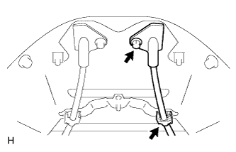
TEMPORARILY INSTALL REAR SHOCK ABSORBER ASSEMBLY LH
-
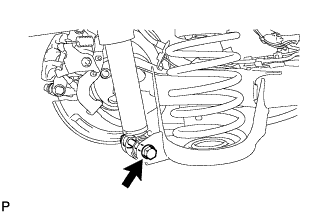
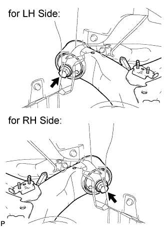
Slowly raise the engine lift and temporarily install the rear shock absorber LH to the rear axle beam assembly with the bolt and nut.
Tech Tips
Support the rear shock absorber assembly LH at a position where it compresses by approximately 20 to 30 mm (0.787 to 1.18 in.).
-
-
TEMPORARILY INSTALL REAR SHOCK ABSORBER ASSEMBLY RH
Tech Tips
Perform the same procedure as for the LH side.
-
INSTALL REAR DISC BRAKE DUST COVER SUB-ASSEMBLY LH
-
INSTALL REAR AXLE HUB AND BEARING ASSEMBLY LH
-
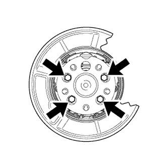
Install the rear axle hub and bearing assembly with the 4 bolts.
- Torque:
- 90 N*m { 918 kgf*cm, 66 ft.*lbf }
-
-
INSTALL REAR DISC BRAKE DUST COVER SUB-ASSEMBLY RH
-
INSTALL REAR AXLE HUB AND BEARING ASSEMBLY RH
Tech Tips
Perform the same procedure as for the LH side.
-
CONNECT NO. 3 PARKING BRAKE CABLE ASSEMBLY
-
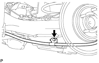
Connect the No. 3 parking brake cable with the bolt.
- Torque:
- 6.0 N*m { 61 kgf*cm, 53 in.*lbf }
-
Attach the clamp.
-
Install the casing cap with the bolt.
- Torque:
- 6.0 N*m { 61 kgf*cm, 53 in.*lbf }
-
-
CONNECT NO. 2 PARKING BRAKE CABLE ASSEMBLY
Tech Tips
Perform the same procedure as for the No. 3 parking brake cable assembly.
-
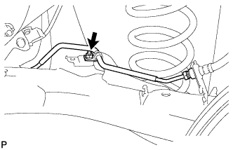
INSTALL NO. 4 REAR BRAKE TUBE
-
Install the No. 4 rear brake tube to the rear axle beam with the nut.
- Torque:
- 8.5 N*m { 87 kgf*cm, 75 in.*lbf }
-
-
INSTALL NO. 3 REAR BRAKE TUBE
Tech Tips
Perform the same procedure as for the No. 4 rear brake tube.
-
CONNECT REAR FLEXIBLE HOSE LH
-
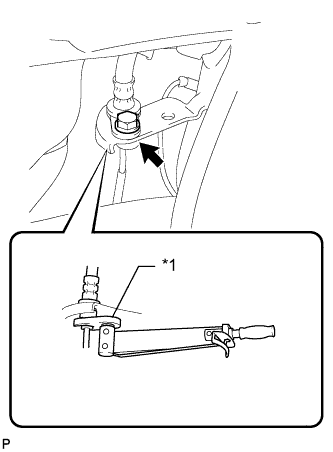
Text in Illustration *1 Union Nut Wrench Connect the rear flexible hose LH with the bolt.
- Torque:
- 19 N*m { 194 kgf*cm, 14 ft.*lbf }
-
Using a union nut wrench, connect the No. 4 rear brake tube to the rear flexible hose LH while holding the rear flexible hose LH with a wrench.
- Torque:
- 15 N*m { 155 kgf*cm, 11 ft.*lbf }
Note
-
Do not kink or damage the brake tube.
-
Do not allow any foreign matter such as dirt and dust to enter the brake tube.
-
Use the formula to calculate special torque values for situations where a union nut wrench is combined with a torque wrench Click here.
-
-
CONNECT REAR FLEXIBLE HOSE RH
-
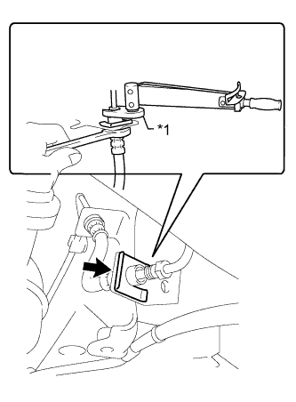
Text in Illustration *1 Union Nut Wrench Connect the rear flexible hose RH with a new clip.
Note
Make sure the clip is completely pushed in.
-
Using a union nut wrench, connect the No. 3 rear brake tube to the rear flexible hose RH while holding the rear flexible hose RH with a wrench.
- Torque:
- 15 N*m { 155 kgf*cm, 11 ft.*lbf }
Note
-
Do not kink or damage the brake tube.
-
Do not allow any foreign matter such as dirt and dust to enter the brake tube.
-
Use the formula to calculate special torque values for situations where a union nut wrench is combined with a torque wrench Click here.
-
-
CONNECT REAR BRAKE FLEXIBLE HOSE (for LH Side)
-
Connect the rear flexible hose with a new clip.
Note
Make sure the clip is completely pushed in.
-
Using a union nut wrench, connect the brake tube to the rear brake flexible hose while holding the rear brake flexible hose with a wrench.
- Torque:
- 15 N*m { 155 kgf*cm, 11 ft.*lbf }
Note
-
Do not kink or damage the brake tube.
-
Do not allow any foreign matter such as dirt and dust to enter the brake tube.
-
Use the formula to calculate special torque values for situations where a union nut wrench is combined with a torque wrench Click here.
-
-
CONNECT REAR BRAKE FLEXIBLE HOSE (for RH Side)
Tech Tips
Perform the same procedure as for the LH side.
-
CONNECT SKID CONTROL SENSOR WIRE (for LH Side)
-
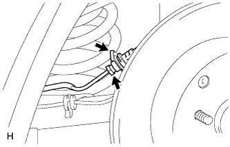
Connect the skid control sensor wire connector to the skid control sensor.
Note
-
To prevent interference with other parts, do not twist the painted line areas of the sensor wire when installing it.
-
Do not twist the sensor wire when installing the clamp.
-
-
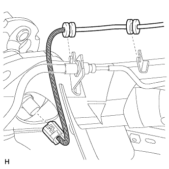
Attach the 2 grommets.
-
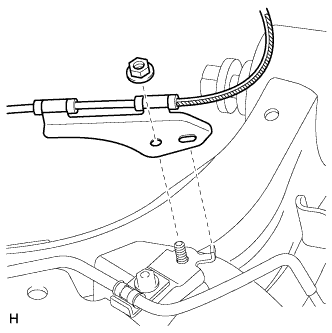
Install the sensor clamp with the nut.
- Torque:
- 8.5 N*m { 87 kgf*cm, 75 in.*lbf }
Note
Do not twist the sensor wire when installing the clamp.
-
-
CONNECT SKID CONTROL SENSOR WIRE (for RH Side)
Tech Tips
Perform the same procedure as for the LH side.
-
INSTALL PARKING BRAKE ASSEMBLY
-
Install the parking brake assembly Click here.
-
-
BLEED BRAKE SYSTEM
Tech Tips
Refer to the Bleeding procedures for the brake system Click here.
-
ADJUST PARKING BRAKE LEVER TRAVEL
Tech Tips
Refer to the Adjust Parking Brake Lever Travel procedures Click here.
-
STABILIZE SUSPENSION
-
Lower the vehicle.
-
Bounce the vehicle up and down several times to stabilize the suspension.
-
-
TIGHTEN REAR AXLE BEAM ASSEMBLY
-
Tighten the left and right bolts of the rear axle beam assembly.
- Torque:
- 135 N*m { 1376 kgf*cm, 99 ft.*lbf }
Note
Make sure that all tires of the vehicle are on the ground and the vehicle is unloaded.
-
-
TIGHTEN REAR SHOCK ABSORBER ASSEMBLY LH
-
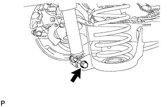
Hold the nut and tighten the bolt.
- Torque:
- 90 N*m { 918 kgf*cm, 66 ft.*lbf }
Note
-
Do not turn the nut.
-
Make sure that all tires of the vehicle are on the ground and the vehicle is unloaded.
-
-
TIGHTEN REAR SHOCK ABSORBER ASSEMBLY RH
Tech Tips
Perform the same procedure as for the LH side.
-
INSTALL REAR HEIGHT CONTROL SENSOR SUB-ASSEMBLY RH (w/ HID Headlight)
-
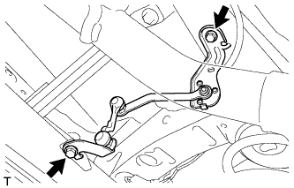
Install the rear height control sensor with the 2 bolts.
- Torque:
- 8.0 N*m { 82 kgf*cm, 71 in.*lbf }
-
Connect the connector.
-
-
INSTALL REAR FLOOR SIDE MEMBER BRACE SUB-ASSEMBLY
-
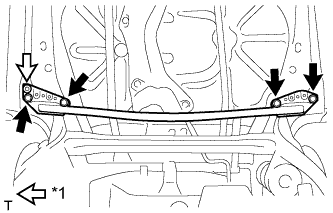
Text in Illustration *1 Clip Attach the clip and install the rear floor side member brace with the 4 bolts.
- Torque:
- 54 N*m { 551 kgf*cm, 40 ft.*lbf }
-
-
INSTALL REAR FLOOR SIDE MEMBER COVER LH
-
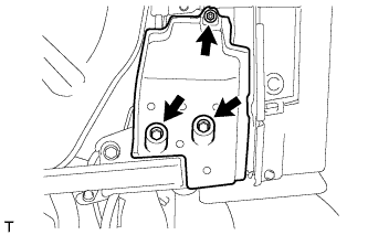
Install the rear floor side member cover with the nut and 2 bolts.
-
-
REMOVE REAR FLOOR SIDE MEMBER COVER RH
-
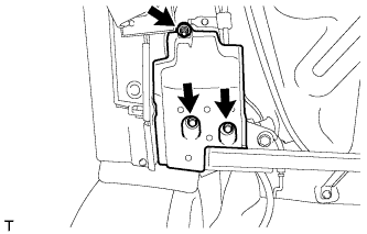
Install the rear floor side member cover with the nut and 2 bolts.
-
-
INSPECT REAR WHEEL ALIGNMENT
-
Inspect the rear wheel alignment Click here.
-
-
PLACE FRONT WHEELS FACING STRAIGHT AHEAD (w/ VSC)
-
INSPECT SPEED SENSOR SIGNAL
-
w/o VSC:
Check the speed sensor signal Click here.
-
w/ VSC:
Check the speed sensor signal Click here.
-
-
INITIALIZE HEIGHT CONTROL SENSOR SIGNAL (w/ HID Headlight)
-
Initialize the height control sensor signal Click here.
-
-
INSPECT AND ADJUST HEADLIGHT AIMING (w/ HID Headlight)
-
Inspect and adjust the headlight aiming Click here.
-