SHIFT LEVER REASSEMBLY

Tech Tips
-
Use the same procedure for RHD and LHD vehicles.
-
The procedure listed below is for LHD vehicles.
-
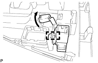
INSTALL SHIFT LOCK CONTROL ECU
-
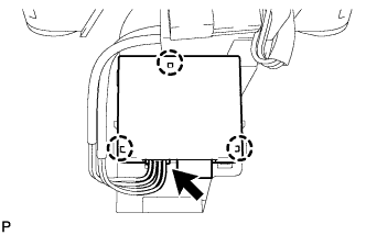
Attach the 3 claws to install the shift lock control ECU to the shift lock control unit.
-
Connect the shift lock solenoid connector to the shift lock control ECU.
-
-
INSTALL POSITION INDICATOR SLIDE COVER
-
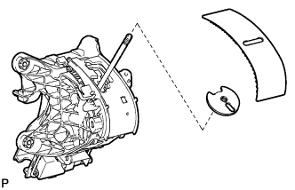
Install the No. 2 position indicator slide cover to the position indicator slide cover.
-
Install the position indicator slide cover together with the No. 2 position indicator slide cover to the position indicator housing.
-
-
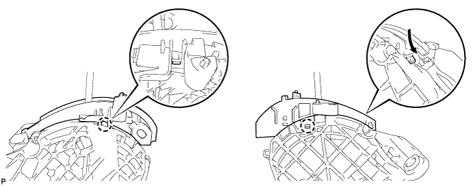
INSTALL LOWER POSITION INDICATOR HOUSING
-
Attach the 2 claws to install the lower position indicator housing to the shift lock control unit.
-
-
INSTALL UPPER POSITION INDICATOR HOUSING
-
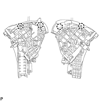
Attach the 4 claws to install the upper position indicator housing to the shift lock control unit.
-
-
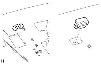
INSTALL POSITION INDICATOR LIGHT BULB
-
Install the cap to the bulb.
-
Install the bulb to the position indicator light wire socket.
-
-
INSTALL INDICATOR LIGHT WIRE SUB-ASSEMBLY
-
Align the wire socket with the key part of the position indicator housing, and install the wire. Then rotate the wire socket clockwise until it locks.
-
Connect the indicator light wire connector to the position indicator housing.
-
-
INSTALL NO. 1 PATTERN SELECT SWITCH ASSEMBLY
-
Attach the 2 claws to install the No. 1 pattern select switch assembly to the position indicator housing assembly.
-
-
INSTALL SHIFT LOCK RELEASE BUTTON COVER
-
Attach the 2 claws to install the shift lock release button cover to the position indicator housing assembly.
-