CONTINUOUSLY VARIABLE TRANSAXLE ASSEMBLY REMOVAL

CAUTION:
The engine assembly with continuously variable transaxle assembly is very heavy. Be sure to follow the procedure described in the repair manual, or the engine lifter may suddenly drop.
-
REMOVE FLYWHEEL HOUSING UNDER COVER
-
Remove the flywheel housing under cover.
-
-
REMOVE DRIVE PLATE AND TORQUE CONVERTER ASSEMBLY SETTING BOLT
-
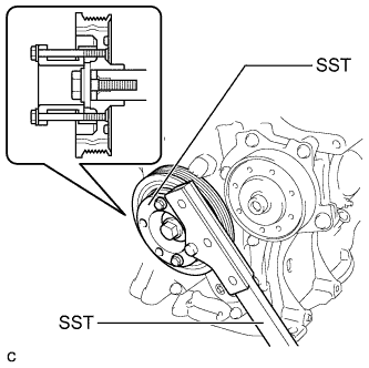
Using SST, hold the crankshaft pulley.
- SST
- 09213-54015
- 09330-00021
Tech Tips
Part number of installation bolt for SST (crankshaft pulley holding tool): 91551-00850 (quantity: 2)
-
Remove the 6 drive plate and torque converter assembly setting bolts.
-
-
REMOVE ENGINE ASSEMBLY WITH TRANSAXLE
-
REMOVE STARTER ASSEMBLY
-
Open the terminal cap.
-
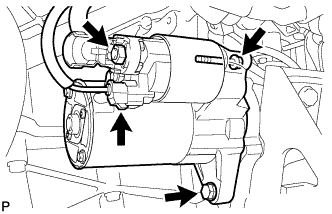
Remove the nut and disconnect the starter wire.
-
Disconnect the connector.
-
Remove the 2 bolts and starter.
-
-
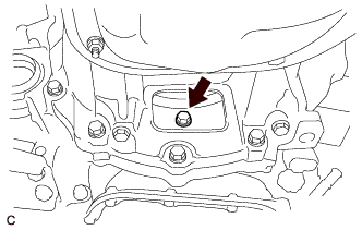
REMOVE FLYWHEEL HOUSING SIDE COVER
-
Remove the flywheel housing side cover from the cylinder block.
-
-
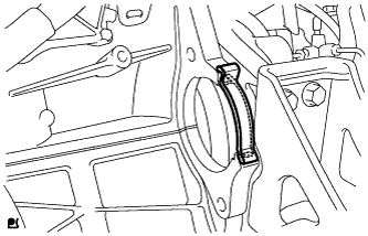
DISCONNECT WATER BY-PASS HOSE
-
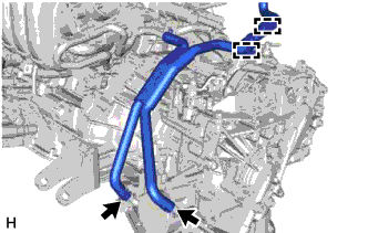
Disconnect the water by-pass hose from the 2 clamps.
-
Slide the 2 clips and disconnect the water by-pass hose from the transmission oil cooler assembly.
-
-
REMOVE GROUND CABLE
-
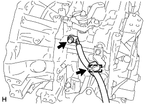
Detach the clamp.
-
Remove the bolt and ground cable.
-
-
DISCONNECT ENGINE WIRE
-
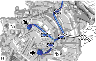
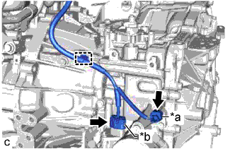
Text in Illustration *a Transmission Revolution Sensor (NOUT) Connector *b Oil Pressure Sensor Connector Disconnect the transmission revolution sensor (NOUT) connector.
-
Disconnect the oil pressure sensor connector.
-
Detach the 5 clamps.
-
Disconnect the park/neutral position switch assembly connector.
-
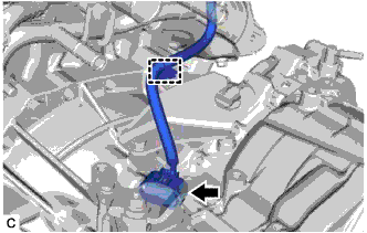
Detach the clamp.
-
Text in Illustration *a Transmission Revolution Sensor (NIN) Connector *b Transmission Wire Connector Disconnect the transmission revolution sensor (NIN) connector.
-
Disconnect the transmission wire connector.
-
Detach the clamp.
-
-
REMOVE CONTINUOUSLY VARIABLE TRANSAXLE ASSEMBLY
-
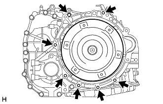
Remove the 7 bolts and continuously variable transaxle assembly from the engine assembly.
Note
To prevent damaging the 2 knock pins, do not pry between the continuously variable transaxle assembly and engine assembly.
-
-
REMOVE TORQUE CONVERTER ASSEMBLY
-
Remove the torque converter assembly from the continuously variable transaxle assembly.
Note
Remove the torque converter assembly from the input shaft horizontally.
-
-
REMOVE CVT OIL PUMP TYPE T OIL SEAL
CAUTION:
-
Do not remove the front oil pump assembly from the continuously variable transaxle assembly main body, as there is a possibility of the entry of dust and foreign matter.
-
Clean the work area, the tools to be used, and other equipment, etc. thoroughly before the operation, as there is the possibility that a continuously variable transaxle assembly malfunction, which may prevent the vehicle from being driven, may occur if dust or fine foreign matter enters the continuously variable transaxle assembly.
-
Do not use cotton work gloves, cloths, paper towels, etc. that may produce lint, dust or foreign matter.
-
Perform the operation as quickly as possible, as dust and foreign matter may enter the continuously variable transaxle assembly while the torque converter assembly is not attached to it.
-
Do not use an air gun until the torque converter assembly has been installed, as it may cause dust and foreign matter to be stirred up.
-
Clean the tips of both the claws of SST and the center bolt.
-
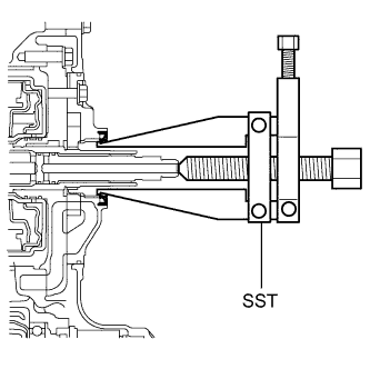
Using SST, remove the CVT oil pump type T oil seal from the continuously variable transaxle assembly.
- SST
- 09308-10010
Note
Pay attention to the angle of the claws when opening them, and ensure that they do not come into contact with the oil pump housing, as there is the possibility that metal particles may be produced if they do.
-
-
REMOVE NO. 1 TRANSMISSION CONTROL CABLE BRACKET
-
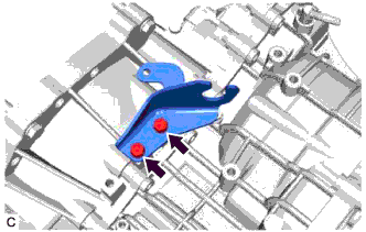
Remove the 2 bolts and No. 1 transmission control cable bracket from the continuously variable transaxle assembly.
-
-
REMOVE FRONT ENGINE MOUNTING BRACKET
-
Remove the 4 bolts and front engine mounting bracket from the continuously variable transaxle assembly.
-
-
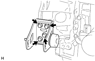
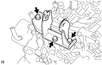
REMOVE REAR ENGINE MOUNTING BRACKET
-
Remove the 3 bolts and rear engine mounting bracket from the continuously variable transaxle assembly.
-
-
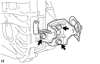
REMOVE ENGINE MOUNTING BRACKET LH
-
Remove the 3 bolts and engine mounting bracket LH from the continuously variable transaxle assembly.
-
-
REMOVE WIRE HARNESS CLAMP BRACKET
-
Remove the water by-pass hose clamp from the water by-pass hose clamp bracket.
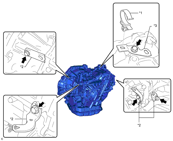
Text in Illustration *1 Water By-pass Hose Clamp *2 Wire Harness Clamp Bracket *3 Water By-pass Hose Clamp Bracket - - -
Remove the 5 bolts, 4 wire harness clamp brackets and water by-pass hose clamp bracket from the continuously variable transaxle assembly.
-
-
REMOVE TRANSMISSION OIL FILLER TUBE STRAIGHT SCREW PLUG
Tech Tips
Perform this procedure only when replacement of the transmission oil filler tube straight screw plug is necessary.
-
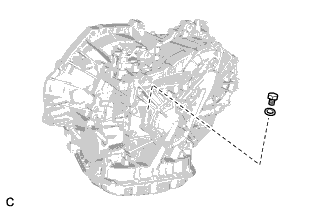
Remove the transmission oil filler tube straight screw plug and gasket from the continuously variable transaxle assembly.
-
-
REMOVE BREATHER PLUG HOSE
Tech Tips
Perform this procedure only when replacement of the breather plug hose is necessary.
-
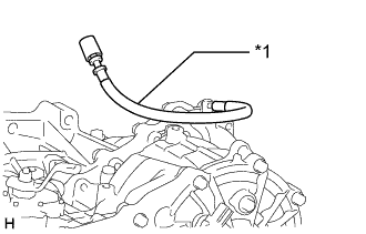
Text in Illustration *1 Breather Plug Hose Remove the breather plug hose from the continuously variable transaxle assembly.
-
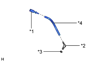
Text in Illustration *1 No. 1 Breather Plug *2 No. 2 Breather Plug *3 O-ring *4 Breather Plug Hose Remove the 2 breather plugs from the breather plug hose.
-
Remove the O-ring from the breather plug.
-
-
INSPECT TORQUE CONVERTER ASSEMBLY
-
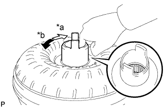
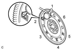
Text in Illustration *a Smooth *b Difficult Inspect the one-way clutch.
-
Press on the spline of the stator with a finger and rotate the spline. Check that the spline rotates smoothly when turned clockwise and rotates with difficulty when turned counterclockwise.
If necessary, clean the torque converter assembly and recheck the one-way clutch. Replace the torque converter assembly if the one-way clutch still fails the inspection.
-
-
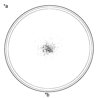
Text in Illustration *a Sample showing maximum allowable amount of powder in fluid *b Full Scale Inspect the torque converter assembly.
If any of the following problems are present, replace the torque converter assembly.
-
A metallic sound is emitted from the torque converter assembly during the stall test or when the shift lever is moved to N.
-
The one-way clutch turns smoothly or difficulty in both directions.
-
The amount of powder in the fluid is more than the sample shown in the illustration (refer to the sample).
Malfunction:
Tech Tips
The sample shows approximately 0.025 liters (0.026 US qts, 0.022 Imp. qts) of fluid in petridish, which has been taken from a torque converter assembly.
-
-
Replace the fluid in the torque converter assembly.
Tech Tips
If the fluid is discolored or has a foul odor, stir the fluid in the torque converter assembly and drain it before replacing the fluid.
-
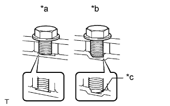
Text in Illustration *a Correct *b Incorrect *c Bottom is damaged Prevent deformation of the torque converter assembly and damage to the oil pump gear.
Note
Make sure that all of the bolts are the same length and that the specified bolts are used.
Tech Tips
If there is any damage to the tip of a bolt for the torque converter assembly or to the bottom of a bolt hole, replace the bolt and torque converter assembly.
-
-
INSPECT DRIVE PLATE AND RING GEAR SUB-ASSEMBLY
-
Check the drive plate for damage.
-
Set up a dial indicator and measure the runout at the 6 areas on the drive plate surface that contact the torque converter assembly.
Maximum runout 0.30 mm (0.0118 in.) If the runout is more than the maximum or the drive plate is damaged, replace the drive plate Click here.
Text in Illustration 
Measurement Point
-