TRANSMISSION CONTROL CABLE ADJUSTMENT

-
INSPECT SHIFT LEVER POSITION
-
When moving the shift lever from P to R with the ignition switch ON and the brake pedal depressed, make sure that the shift lever moves smoothly and correctly into position.
-
Start the engine and make sure that the vehicle moves forward after moving the shift lever from N to D and moves in reverse after moving the shift lever to R.
If the operation cannot be performed as specified, inspect the park/neutral position switch assembly and check the shift lever assembly installation condition.
-
-
REMOVE LOWER NO. 1 INSTRUMENT PANEL FINISH PANEL
-
ADJUST SHIFT LEVER POSITION
-
Apply the parking brake and move the shift lever to N.
-
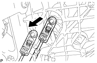
Disconnect the end of the transmission control cable assembly from the shift lever assembly.
-
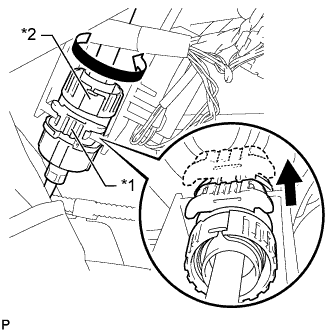
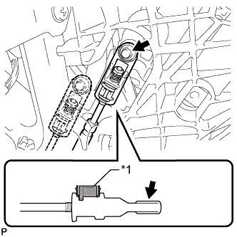
Text in Illustration *1 Stopper *2 Nut Pull out the stopper of the transmission control cable assembly.
Note
Do not remove the stopper. If the stopper is removed, reinstall it to its original position.
-
Rotate the nut counterclockwise approximately 180° and, while holding the nut in that position, disconnect the transmission control cable assembly from the shift lever assembly.
Note
Do not over-rotate the nut as it will come off the internal spring and the transmission control cable assembly will not be reusable.
-
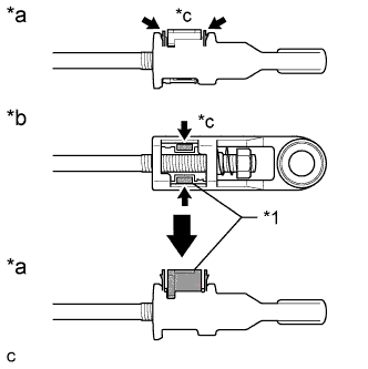
Text in Illustration *1 Lock Piece *a Side View *b Bottom View *c Push Push the 2 claws together at the top of the transmission control cable lock piece. While holding the 2 claws together, push the 2 lugs on the bottom of the lock piece toward each other and upward to pull out the lock piece.
-
Turn the nut of the transmission control cable assembly 180° counterclockwise. While holding the nut in place, push in the stopper until the stopper clicks twice.
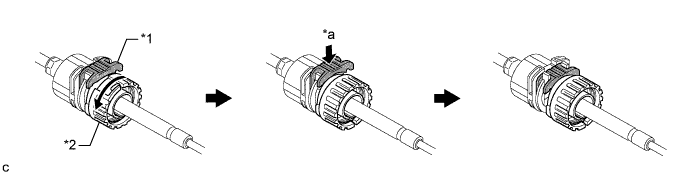
Text in Illustration *1 Stopper *2 Nut *a Push in - - -
Install the outer part of the transmission control cable assembly to the shift lever assembly. Check that the spring is positioned at "A" and push in the stopper.
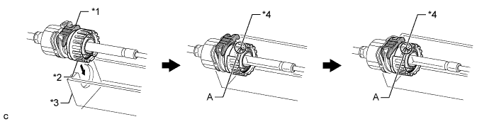
Text in Illustration *1 Stopper *2 Nut *3 Shift Lever Assembly *4 Spring Tech Tips
If the stopper cannot be pushed in, slightly turn the nut clockwise and then push in the stopper again.
-
Coat the end of the transmission control cable assembly with MP grease.
-
Connect the end of the transmission control cable assembly to the shift lever assembly.
Text in Illustration *1 Lock Piece 
MP grease Note
-
Make sure that the lock piece is pulled up.
-
Push on the end of the cable all the way to the base of the pin.
-
-
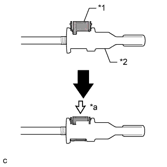
Text in Illustration *1 Lock Piece *2 Adjuster Case *a Push in Push the lock piece into the adjuster case.
Note
Securely push in the lock piece until it locks.
-
After adjusting the shift lever position, check the operation and function of the shift lever. If there is a problem, adjust the position again.
-
-
INSTALL LOWER NO. 1 INSTRUMENT PANEL FINISH PANEL