PARK / NEUTRAL POSITION SWITCH INSTALLATION
-
INSTALL PARK/NEUTRAL POSITION SWITCH ASSEMBLY
-
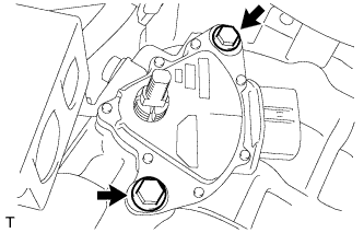
Install the park/neutral position switch to the continuously variable transaxle.
-
Temporarily install the 2 bolts.
-
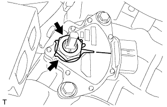
Install a new lock plate and the lock nut to the park/neutral position switch.
- Torque:
- 6.9 N*m { 70 kgf*cm, 61 in.*lbf }
-
Temporarily install the control shaft lever.
-
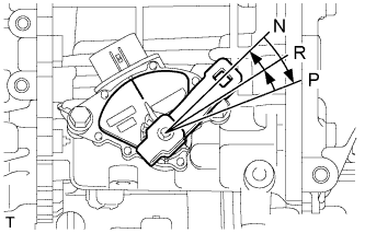
Turn the lever clockwise until it stops, and then turn it counterclockwise 2 notches.
-
Remove the control shaft lever.
-
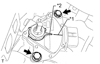
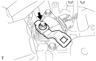
Align the protrusion with the neutral basic line.
-
Hold the switch in that position and tighten the 2 bolts.
- Torque:
- 5.4 N*m { 55 kgf*cm, 48 in.*lbf }
Text in Illustration *1 Neutral Basic Line *2 Protrusion -
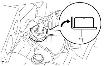
Text in Illustration *1 Lock Plate Using a screwdriver, bend the tabs of the lock plate.
-
Install the control shaft lever with the washer and nut.
- Torque:
- 13 N*m { 130 kgf*cm, 9 ft.*lbf }
-
Connect the park/neutral position switch connector.
-
-
CONNECT TRANSMISSION CONTROL CABLE ASSEMBLY
-
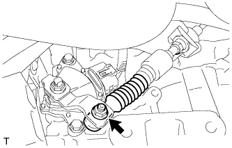
Connect the transmission control cable to the control shaft lever with the nut.
- Torque:
- 12 N*m { 122 kgf*cm, 9 ft.*lbf }
-
-
INSPECT SHIFT LEVER POSITION
-
When moving the shift lever from P to R with the ignition switch ON and the brake pedal depressed, make sure that the shift lever moves smoothly and correctly into position.
-
Start the engine and make sure that the vehicle moves forward after moving the shift lever from N to D and moves in reverse after moving the shift lever to R. If the operation cannot be performed as specified, inspect the park/neutral position switch assembly and check the shift lever assembly installation condition.
-
-
ADJUST SHIFT LEVER POSITION
-
Remove the lower No. 1 instrument panel finish panel Click here.
-
Apply the parking brake and move the shift lever to N.
-
Disconnect the end of the transmission control cable assembly from the shift lever assembly.
-
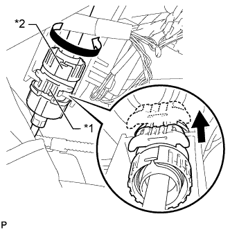
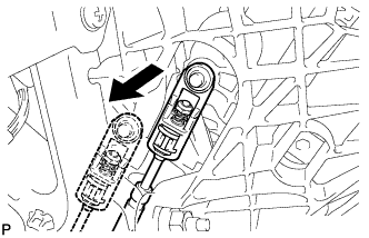
Text in Illustration *1 Stopper *2 Nut Pull out the stopper of the transmission control cable.
Note
Do not remove the stopper. If the stopper is removed, reinstall it to its original position.
-
Rotate the nut counterclockwise approximately 180° and, while holding the nut in that position, disconnect the transmission control cable from the shift lever retainer.
Note
Do not over-rotate the nut as it will come off the internal spring and the transmission control cable will not be reusable.
-
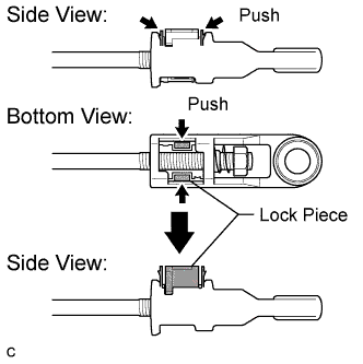
Push the 2 claws together at the top of the transmission control cable lock piece. While holding the 2 claws together, push the 2 lugs on the bottom of the lock piece toward each other and upward to pull out the lock piece.
-
Turn the nut of the transmission control cable 180° counterclockwise. While holding the nut in place, push in the stopper until the stopper clicks twice.
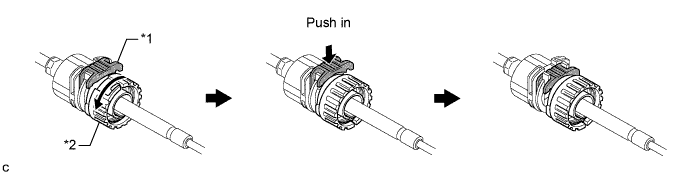
Text in Illustration *1 Stopper *2 Nut -
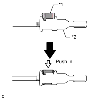
Install the outer part of the transmission control cable to the shift lever retainer. Check that the spring is positioned at "A" and push in the stopper.
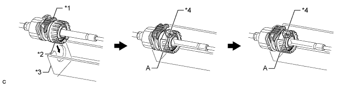
Text in Illustration *1 Stopper *2 Nut *3 Shift Lever Retainer *4 Spring Tech Tips
If the stopper cannot be pushed in, slightly turn the nut clockwise and then push in the stopper again.
-
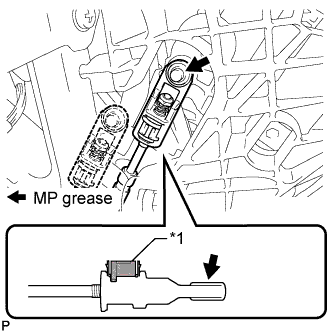
Coat the end of the cable with MP grease.
-
Connect the end of the cable to the shift lever.
Text in Illustration *1 Lock Piece Note
-
Make sure that the lock piece is pulled up.
-
Push on the end of the cable all the way to the base of the pin.
-
-
Text in Illustration *1 Lock Piece *2 Adjuster Case Push the lock piece into the adjuster case.
Note
Securely push in the lock piece until it locks.
-
After adjusting the shift lever position, check the operation and function of the shift lever. If there is a problem, adjust the position again.
-
Install the lower No. 1 instrument panel finish panel Click here.
-
-
INSTALL AIR CLEANER CASE SUB-ASSEMBLY
-
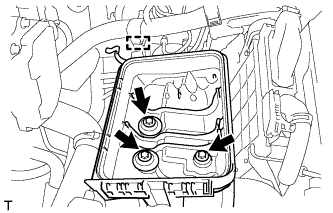
Install the air cleaner case with the 3 bolts.
- Torque:
- 7.0 N*m { 71 kgf*cm, 62 in.*lbf }
-
Attach the wire harness clamp to the air cleaner case.
-
-
INSTALL AIR CLEANER CAP AND HOSE
-
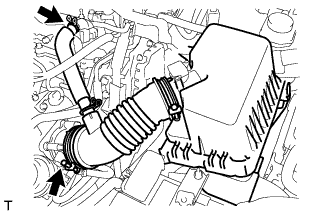
Connect the air cleaner cap with the band.
-
Connect the PCV hose.
-
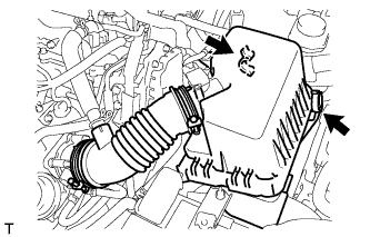
Connect the 2 clamps.
-
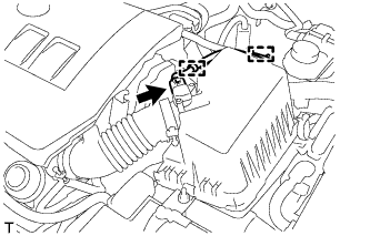
Attach the 2 clamps and connect the wire harness.
-
Connect the mass air flow meter connector.
-
-
INSTALL NO. 2 CYLINDER HEAD COVER
-
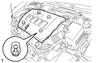
Attach the 4 clips to install the cover.
Note
-
Be sure to attach the clips securely.
-
Do not apply excessive force or hit the cover to attach the clips. This may cause the cover to break.
-
-
-
INSPECT PARK/NEUTRAL POSITION SWITCH ASSEMBLY
-
Apply the parking brake and turn the ignition switch to ON.
-
Depress the brake pedal and check that the engine can be started when the shift lever is in N or P, but does not start when the shift lever is in other positions.
-
Check that the back-up light illuminates when the shift lever is in R, but does not function when the shift lever is in other positions.
If a malfunction or failure is found, check the park/ neutral position switch.
-