CONTINUOUSLY VARIABLE TRANSAXLE ASSEMBLY INSTALLATION

-
INSTALL NO. 2 TRANSAXLE CASE PLUG
Tech Tips
Perform this procedure only when replacement of the No. 2 transaxle case plug is necessary.
-
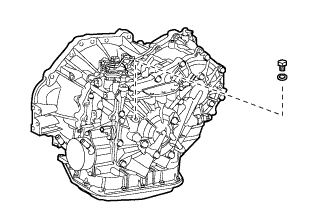
Install the No. 2 transaxle case plug and a new gasket to the continuously variable transaxle assembly.
- Torque:
- 7.5 N*m { 76 kgf*cm, 66 in.*lbf }
-
-
INSTALL CVT OIL PUMP TYPE T OIL SEAL
-
Ensure that there is no dirt or foreign matter on your hands, and then apply genuine TOYOTA MP grease No.2 to the entire periphery of the lip of a new CVT oil pump type T oil seal.
-
Temporarily attach the CVT oil pump type T oil seal by pressing it onto the installation surface of the oil pump housing manually.
-
Clean the oil seal contact section of the SST and the area around it.
-
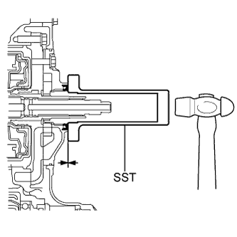
Using the SST, drive the CVT oil pump type T oil seal in evenly, as far as the side surface of the oil pump housing.
- SST
- 09309-36010
Note
-
Drive the oil seal in gradually, while visually checking the parallelism.
-
After the installation, confirm that the oil seal has been driven in as far as the side surface of the oil pump housing.
-
Wipe off any grease that has oozed out with your hand.
Tech Tips
The oil seal should be driven in between 0 and 0.5mm (as measured from the side surface of the oil pump housing).
-
-
INSTALL TORQUE CONVERTER CLUTCH ASSEMBLY
-
Clean the torque converter clutch setting bolt holes.
-
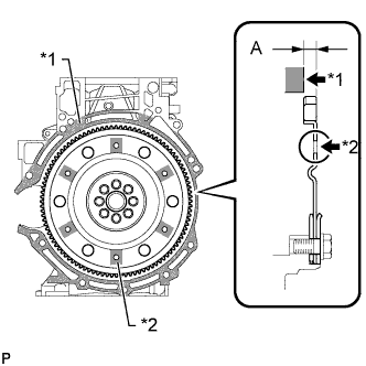
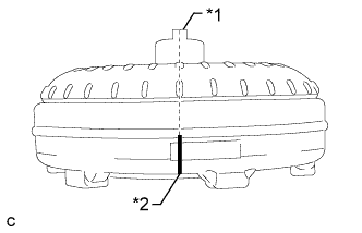
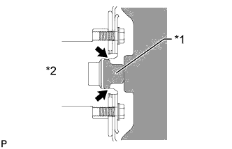
Using a vernier caliper and straightedge, measure dimension "A" between the transaxle fitting surface of the engine*1 and the torque converter clutch fitting surface of the drive plate*2. (#)
-
Text in Illustration *1 Matchmark *2 Groove Turn the front oil pump drive gear so that the groove is at the top and put a matchmark on the housing.
-
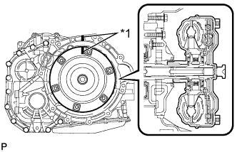
Text in Illustration *1 Key *2 Matchmark Put a matchmark on the torque converter clutch so that the position of its key is clearly indicated.
-
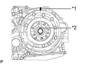
Text in Illustration *1 Matchmark Align the matchmark on the housing with the one on the torque converter clutch and mesh the splines of the input shaft with the turbine runner splines.
Note
Install the torque converter clutch horizontally to the input shaft.
-
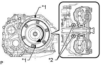
Text in Illustration *1 Matchmark *2 Oil Seal Rotate the torque converter clutch and mesh the splines of the stator shaft with the stator splines.
Note
-
Do not damage the oil seal.
-
Install the torque converter clutch horizontally to the input shaft.
Tech Tips
Rotate the torque converter clutch approximately 180°.
-
-
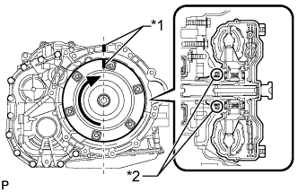
Text in Illustration *1 Matchmark *2 Oil Seal Rotate the torque converter clutch again, align the matchmark on the housing with the one on the torque converter clutch and insert the key of the torque converter clutch into the groove of the oil pump drive gear.
Note
-
Do not push the torque converter clutch excessively when rotating it.
-
Do not damage the oil seal.
-
Install the torque converter clutch horizontally to the input shaft.
-
-
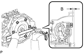
Using a vernier caliper and straightedge, measure dimension "B" shown in the illustration and check that dimension "B" is more than dimension "A" (which was measured in step (#)).
Standard A + 1 mm (0.0394 in.) or more Note
Subtract the thickness of the straightedge from the measured value to gain dimension "B".
-
-
INSTALL WIRE HARNESS CLAMP BRACKET
-
Install the 5 wire harness clamp brackets to the continuously variable transaxle with the 5 bolts.
- Torque:
- 13 N*m { 130 kgf*cm, 9 ft.*lbf }
-
Attach the water by-pass hose clamp to the wire harness clamp bracket.
-
-
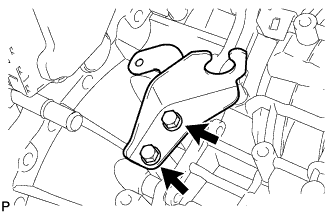
INSTALL NO. 1 TRANSMISSION CONTROL CABLE BRACKET
-
Install the No. 1 transmission control cable bracket to the continuously variable transaxle with the 2 bolts.
- Torque:
- 12 N*m { 122 kgf*cm, 9 ft.*lbf }
-
-
INSTALL CONTINUOUSLY VARIABLE TRANSAXLE ASSEMBLY
-
Apply clutch spline grease to the surface of the torque converter clutch centerpiece that contacts the crankshaft.
Clutch spline grease Toyota Genuine Clutch Spline Grease or equivalent Maximum grease amount Approximately 1 g (0.0353 oz.) Text in Illustration *1 Torque converter clutch Centerpiece *2 Crankshaft -
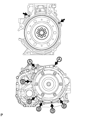
Confirm that the 2 knock pins are on the surface of the engine cylinder block that contacts the transaxle.
-
Maintain the engine and continuously variable transaxle assembly in a horizontal position, align the knock pins with the holes on the continuously variable transaxle assembly and install the continuously variable transaxle assembly with the 7 bolts shown in the illustration.
- Torque:
- 30 N*m { 301 kgf*cm, 22 ft.*lbf }
Tech Tips
-
Bolt A: Install from the transaxle side.
-
Bolt B: Install from the engine side.
Note
Make sure that the torque converter clutch rotates.
-
-
INSTALL DRIVE PLATE AND TORQUE CONVERTER CLUTCH SETTING BOLT
-
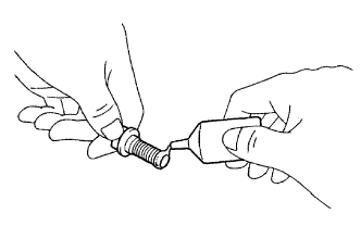
Apply a few drops of adhesive to 2 or 3 threads of the tips of the 6 torque converter clutch setting bolts.
Adhesive Toyota Genuine Adhesive 1324, Three Bond 1324 or equivalent -
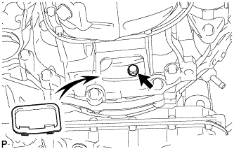
Turn the crankshaft to gain access to the installation locations of the 6 torque converter clutch setting bolts and install each bolt while holding the crankshaft pulley bolt with a wrench.
- Torque:
- 28 N*m { 286 kgf*cm, 21 ft.*lbf }
Note
Install the black bolt first, and then the 5 silver bolts.
-
Install the flywheel housing under cover.
-
-
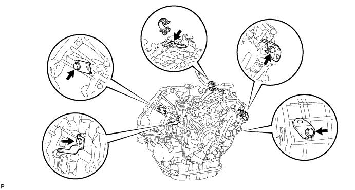
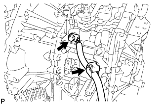
CONNECT ENGINE WIRE
-
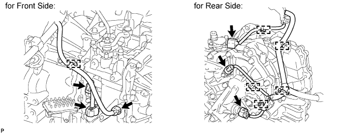
for Front Side:
Attach the wire harness clamp and connect the 2 revolution sensor connectors and transmission wire connector to the continuously variable transaxle.
-
for Rear Side:
Attach the 5 wire harness clamps and connect the oil pressure sensor connector, revolution sensor connector and park/neutral position switch connector to the continuously variable transaxle.
-
-
INSTALL GROUND CABLE
-
Install the ground cable to the continuously variable transaxle with the bolt.
- Torque:
- 13 N*m { 130 kgf*cm, 9 ft.*lbf }
-
Attach the clamp.
-
-
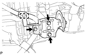
INSTALL REAR ENGINE MOUNTING BRACKET
-
Install the rear engine mounting bracket to the continuously variable transaxle with the 3 bolts.
- Torque:
- 45 N*m { 459 kgf*cm, 33 ft.*lbf }
-
Attach the engine wire clamp to the rear engine mounting bracket.
-
-
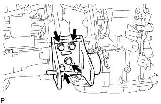
INSTALL FRONT ENGINE MOUNTING BRACKET
-
Install the front engine mounting bracket to the continuously variable transaxle with the 4 bolts.
- Torque:
- 64 N*m { 653 kgf*cm, 47 ft.*lbf }
-
-
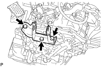
INSTALL ENGINE MOUNTING BRACKET LH
-
Install the engine mounting bracket LH to the continuously variable transaxle with the 3 bolts.
- Torque:
- 64 N*m { 653 kgf*cm, 47 ft.*lbf }
-
-
INSTALL STARTER ASSEMBLY
-
Install the starter with the 2 bolts.
- Torque:
- 37 N*m { 380 kgf*cm, 27 ft.*lbf }
-
Connect the connector.
-
Connect the starter wire with the nut.
- Torque:
- 9.8 N*m { 100 kgf*cm, 87 in.*lbf }
-
Close the terminal cap.
-
-
INSTALL TRANSMISSION OIL COOLER ASSEMBLY
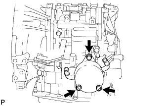
-
Coat 2 new O-rings with CVT fluid FE and install them to the transmission oil cooler.
-
Install the transmission oil cooler to the continuously variable transaxle with the 3 bolts.
- Torque:
- 21 N*m { 214 kgf*cm, 15 ft.*lbf }
-
-
CONNECT WATER BY-PASS HOSE
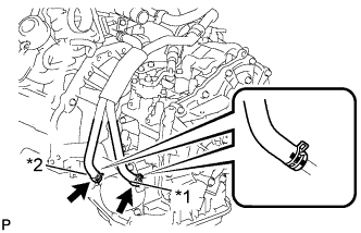
Text in Illustration *1 Green Paint Mark *2 Red Paint Mark
-
Connect the 2 water by-pass hoses to the transmission oil cooler.
Note
Make sure the paint marks and pinching portion of each clip are facing the direction shown in the illustration.
-
-
INSTALL ENGINE ASSEMBLY WITH TRANSAXLE
-
Install the engine with transaxle Click here.
-
-
RESET MEMORY
Tech Tips
Perform Reset Memory (CVT initialization) when replacing the continuously variable transaxle assembly Click here.