CONTINUOUSLY VARIABLE TRANSAXLE SYSTEM, Diagnostic DTC:P0962, P0963, P0966, P0967
| DTC Code | DTC Name |
|---|---|
| P0962 | Pressure Control Solenoid "A" Control Circuit Low (Shift Solenoid Valve DS1) |
| P0963 | Pressure Control Solenoid "A" Control Circuit High (Shift Solenoid Valve DS1) |
| P0966 | Pressure Control Solenoid "B" Control Circuit Low (Shift Solenoid Valve DS2) |
| P0967 | Pressure Control Solenoid "B" Control Circuit High (Shift Solenoid Valve DS2) |
DESCRIPTION
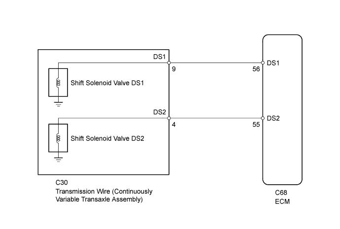
Using shift solenoid valve DS1 (inflow to the primary pulley) and shift solenoid valve DS2 (outflow from the primary pulley), the ECM controls the line pressure and fluid volume input to and output from the primary pulley according to the vehicle speed and accelerator pedal angle. As a fail-safe function, if a solenoid valve is shorted or open, the ECM stops current to the faulty solenoid valve.
| DTC Code | DTC Detection Condition
|
Trouble Area |
|---|---|---|
| P0962 |
|
|
| P0963 |
|
|
| P0966 |
|
|
| P0967 |
|
|
MONITOR DESCRIPTION
These DTCs indicate an open or short circuit in the shift solenoid valve DS1 or DS2 circuit. When there is an open or short circuit in the shift solenoid valve DS1 or DS2 circuits, the ECM detects the problem, illuminates the MIL and stores the DTC.
WIRING DIAGRAM
INSPECTION PROCEDURE
PROCEDURE
-
PERFORM ACTIVE TEST USING INTELLIGENT TESTER (CONTROL THE SHIFT POSITION)
-
Connect the intelligent tester to the DLC3.
-
Turn the ignition switch to ON.
-
Turn the intelligent tester on.
-
Enter the following menus: Powertrain / Engine and ECT / Active Test.
-
In accordance with the display on the tester, perform the Active Test.
Engine and ECT Tester Display Test Part Control Range Diagnostic Note Control the Shift Position Operates the shift solenoid valves to allow the gear ratio to be manually selected [1st - 2nd - 3rd - 4th - 5th]
Reference gear ratios:
1st (2.4) - 2nd (1.5) - 3rd (1.0) - 4th (0.7) - 5th (0.43)
-
Press "→" button: Shift up
-
Press "←" button: Shift down
Used to check the operation of the shift solenoid valves.
Note
Performing this test at speeds other than those specified in "Vehicle Condition" will damage the transaxle.
[Vehicle Condition]
Vehicle speed: 20 to 45 km/h (10.8 to 24.3 mph)
Result Result Proceed to Gear ratio does not change A Gear ratio changes B -
B 
A 
-
-
INSPECT TRANSMISSION WIRE (SHIFT SOLENOID VALVE DS1 AND DS2)
-
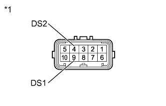
Text in Illustration *1 Component without harness connected
(Transmission Wire)
Disconnect the transmission wire connector.
-
Measure the resistance according to the value(s) in the table below.
Standard Resistance Tester Connection Condition Specified Condition 4 (DS2) - Body ground 20°C (68°F) 11 to 13 Ω 9 (DS1) - Body ground 20°C (68°F) 11 to 13 Ω
NG
OK
-
-
CHECK HARNESS AND CONNECTOR (TRANSMISSION WIRE - ECM)
-
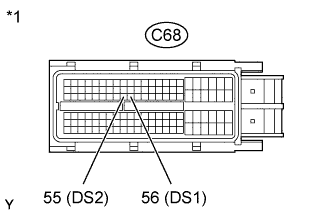
Text in Illustration *1 Front view of wire harness connector
(to ECM)
Disconnect the ECM connector.
-
Measure the resistance according to the value(s) in the table below.
Standard Resistance Tester Connection Condition Specified Condition C68-55 (DS2) - Body ground 20°C (68°F) 11 to 13 Ω C68-56 (DS1) - Body ground 20°C (68°F) 11 to 13 Ω
NG 
REPAIR OR REPLACE HARNESS OR CONNECTOR
OK
-
-
REPLACE ECM
-
Replace the ECM Click here.
NEXT
-
-
PERFORM INITIALIZATION
Note
-
Performing reset memory will clear the learned values of both the yaw rate sensor (deceleration sensor 0 point calibration) and CVT oil pressure (CVT oil pressure calibration). Make sure to perform reset memory, yaw rate sensor 0 point calibration and CVT oil pressure calibration when replacing any of the parts shown in the following table:
Replaced Part
-
Continuously variable transaxle assembly
-
ECM
-
Oil pressure sensor
-
Yaw rate sensor
-
-
After performing reset memory, always perform yaw rate sensor (deceleration sensor 0 point) calibration first, and then CVT oil pressure calibration.
-
Always perform 0 point calibration with the vehicle on level ground.
-
Do not shake or vibrate the vehicle during 0 point calibration.
-
Using the intelligent tester, perform reset memory, deceleration sensor 0 point calibration and CVT oil pressure calibration Click here.
-
Check that no DTC is stored.
NEXT 
END
-
-
REPLACE ECM
-
Replace the ECM Click here.
NEXT
-
-
PERFORM INITIALIZATION
Note
-
Performing reset memory will clear the learned values of both the yaw rate sensor (deceleration sensor 0 point calibration) and CVT oil pressure (CVT oil pressure calibration). Make sure to perform reset memory, yaw rate sensor 0 point calibration and CVT oil pressure calibration when replacing any of the parts shown in the following table:
Replaced Part
-
Continuously variable transaxle assembly
-
ECM
-
Oil pressure sensor
-
Yaw rate sensor
-
-
After performing reset memory, always perform yaw rate sensor (deceleration sensor 0 point) calibration first, and then CVT oil pressure calibration.
-
Always perform 0 point calibration with the vehicle on level ground.
-
Do not shake or vibrate the vehicle during 0 point calibration.
-
Using the intelligent tester, perform reset memory, deceleration sensor 0 point calibration and CVT oil pressure calibration Click here.
-
Check that no DTC is stored.
NEXT
END
-
-
REPLACE CONTINUOUSLY VARIABLE TRANSAXLE ASSEMBLY
-
Replace the continuously variable transaxle assembly Click here.
NEXT
-
-
PERFORM INITIALIZATION
Note
-
Performing reset memory will clear the learned values of both the yaw rate sensor (deceleration sensor 0 point calibration) and CVT oil pressure (CVT oil pressure calibration). Make sure to perform reset memory, yaw rate sensor 0 point calibration and CVT oil pressure calibration when replacing any of the parts shown in the following table:
Replaced Part
-
Continuously variable transaxle assembly
-
ECM
-
Oil pressure sensor
-
Yaw rate sensor
-
-
After performing reset memory, always perform yaw rate sensor (deceleration sensor 0 point) calibration first, and then CVT oil pressure calibration.
-
Always perform 0 point calibration with the vehicle on level ground.
-
Do not shake or vibrate the vehicle during 0 point calibration.
-
Using the intelligent tester, perform reset memory, deceleration sensor 0 point calibration and CVT oil pressure calibration Click here.
-
Check that no DTC is stored.
NEXT
END
-