CONTINUOUSLY VARIABLE TRANSAXLE SYSTEM, Diagnostic DTC:P0705
| DTC Code | DTC Name |
|---|---|
| P0705 | Transmission Range Sensor Circuit Malfunction (PRNDL Input) |
DESCRIPTION
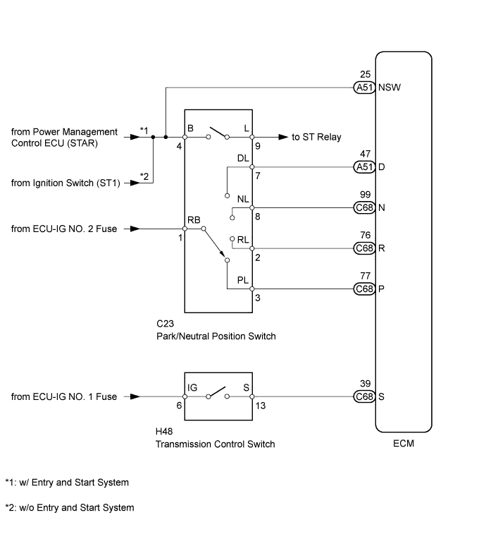
The Park/Neutral Position (PNP) switch detects the shift lever position and sends signals to the ECM.
| DTC Code | DTC Detection Condition
|
Trouble Area |
|---|---|---|
| P0705 |
|
|
MONITOR DESCRIPTION
This DTC indicates a problem with the park/neutral position switch or the wire harness in the park/neutral position switch circuit.
The park/neutral position switch detects the shift lever position and sends a signal to the ECM.
For security, the park/neutral position switch detects the shift lever position so that the engine can be started only when the shift lever is in P or N.
The park/neutral position switch sends a signal to the ECM according to the shift lever position (P, R, N, D or M).
The ECM determines that there is a problem with the switch or related parts if it receives more than 1 position signal simultaneously. The ECM will illuminate the MIL and store the DTC.
WIRING DIAGRAM
INSPECTION PROCEDURE
-
DATA LIST
Tech Tips
Using the intelligent tester to read the Data List allows the values or states of switches, sensors, actuators and other items to be read without removing any parts. This non-intrusive inspection can be very useful because intermittent conditions or signals may be discovered before parts or wiring is disturbed. Reading the Data List information early in troubleshooting is one way to save diagnostic time.
Note
In the table below, the values listed under "Normal Condition" are reference values. Do not depend solely on these reference values when deciding whether a part is faulty or not.
-
Warm up the engine.
-
Turn the ignition switch off.
-
Connect the intelligent tester to the DLC3.
-
Turn the ignition switch to ON.
-
Turn the intelligent tester on.
-
Enter the following menus: Powertrain / Engine and ECT / Data List.
-
According to the display on the tester, read the Data List.
Engine and ECT Tester Display Measurement Item/Range Normal Condition Diagnostic Note Neutral Position SW Signal PNP switch status/
ON or OFF
-
ON: Shift lever in P or N
-
OFF: Shift lever not in P or N
When the shift lever position displayed on the intelligent tester differs from the actual position, the adjustment of the PNP switch or shift cable may be incorrect. Shift SW Status (P Range) PNP switch status/
ON or OFF
-
ON: Shift lever in P
-
OFF: Shift lever not in P
Shift SW Status (R Range) PNP switch status/
ON or OFF
-
ON: Shift lever in R
-
OFF: Shift lever not in R
Shift SW Status (N Range) PNP switch status/
ON or OFF
-
ON: Shift lever in N
-
OFF: Shift lever not in N
Sports Shift Up SW Sport shift up switch status/
ON or OFF
-
ON: Shift lever held in "+" (up-shift)
-
OFF: Shift lever not held in "+" (up-shift)
-
-
ON: "+" shift paddle operated and held (up-shift)
-
OFF: "+" shift paddle not operated (up-shift)
Sports Shift Down SW Sport shift down switch status/
ON or OFF
-
ON: Shift lever held in "-" (down-shift)
-
OFF: Shift lever not held in "-" (down-shift)
-
-
ON: "-" shift paddle operated and held (down-shift)
-
OFF: "-" shift paddle not operated (down-shift)
Sports Mode Selection SW Sport mode select switch status/
ON or OFF
-
ON: Shift lever in M, "+" or "-"
-
OFF: Shift lever not in M, "+" or "-"
- Shift SW Status (D Range) PNP switch status/
ON or OFF
-
ON: Shift lever in D
-
OFF: Shift lever not in D
When the shift lever position displayed on the intelligent tester differs from the actual position, the adjustment of the PNP switch or shift cable may be incorrect. -
-
PROCEDURE
-
CHECK PARK/NEUTRAL POSITION SWITCH ASSEMBLY (POWER SOURCE)
-
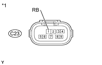
Text in Illustration *1 Front view of wire harness connector
(to Park/Neutral Position Switch)
Disconnect the park/neutral position switch connector.
-
Measure the voltage according to the value(s) in the table below.
Standard Voltage Tester Connection Switch Condition Specified Condition C23-1 (RB) - Body ground Ignition switch ON 11 to 14 V C23-1 (RB) - Body ground Ignition switch off Below 1 V
NG 
REPAIR OR REPLACE HARNESS OR CONNECTOR (PARK/NEUTRAL POSITION SWITCH - BATTERY)
OK 
-
-
CHECK HARNESS AND CONNECTOR (ECM OUTPUT SIGNAL)
-
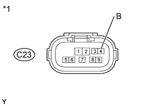
Text in Illustration *1 Front view of wire harness connector
(to Park/Neutral Position Switch)
Disconnect the park/neutral position switch connector.
-
Measure the voltage according to the value(s) in the table below.
Standard Voltage Tester Connection Switch Condition Specified Condition C23-4 (B) - Body ground Ignition switch ON 11 to 14 V C23-4 (B) - Body ground Ignition switch off Below 1 V
NG 
CHECK HARNESS AND CONNECTOR (PARK/NEUTRAL POSITION SWITCH - ECM) Click here
OK
-
-
INSPECT PARK/NEUTRAL POSITION SWITCH ASSEMBLY
-
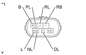
Text in Illustration *1 Component without harness connected
(Park/Neutral Position Switch)
Disconnect the park/neutral position switch connector.
-
Measure the resistance according to the value(s) in the table below.
Standard Resistance Tester Connection Condition Specified Condition
-
1 (RB) - 3 (PL)
-
4 (B) - 9 (L)
Shift lever in P Below 1 Ω 1 (RB) - 2 (RL) Shift lever in R Below 1 Ω
-
1 (RB) - 8 (NL)
-
4 (B) - 9 (L)
Shift lever in N Below 1 Ω 1 (RB) - 7 (DL) Shift lever in D, M, "+" or "-" Below 1 Ω
-
1 (RB) - 3 (PL)
-
4 (B) - 9 (L)
Shift lever not in P 10 kΩ or higher 1 (RB) - 2 (RL) Shift lever not in R 10 kΩ or higher
-
1 (RB) - 8 (NL)
-
4 (B) - 9 (L)
Shift lever not in N 10 kΩ or higher 1 (RB) - 7 (DL) Shift lever not in D, M, "+" or "-" 10 kΩ or higher -
NG
REPLACE PARK/NEUTRAL POSITION SWITCH ASSEMBLY Click here
OK
-
-
CHECK TRANSMISSION CONTROL SWITCH (POWER SOURCE)
-
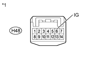
Text in Illustration *1 Front view of wire harness connector
(to Transmission Control Switch)
Disconnect the transmission control switch connector.
-
Measure the voltage according to the value(s) in the table below.
Standard Voltage Tester Connection Switch Condition Specified Condition H48-6 (IG) - Body ground Ignition switch ON 11 to 14 V H48-6 (IG) - Body ground Ignition switch off Below 1 V
NG
REPAIR OR REPLACE HARNESS OR CONNECTOR (TRANSMISSION CONTROL SWITCH - BATTERY)
OK
-
-
INSPECT TRANSMISSION CONTROL SWITCH
-
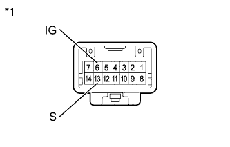
Text in Illustration *1 Component without harness connected
(Transmission Control Switch)
Disconnect the transmission control switch connector.
-
Measure the resistance according to the value(s) in the table below.
Standard Resistance Tester Connection Condition Specified Condition 6 (IG) - 13 (S) Shift lever in M, "+" or "-" Below 1 Ω 6 (IG) - 13 (S) Shift lever not in M, "+" or "-" 10 kΩ or higher
NG
REPLACE TRANSMISSION CONTROL SWITCH (SHIFT LOCK CONTROL UNIT ASSEMBLY) Click here
OK
-
-
CHECK HARNESS AND CONNECTOR (BATTERY - ECM)
-
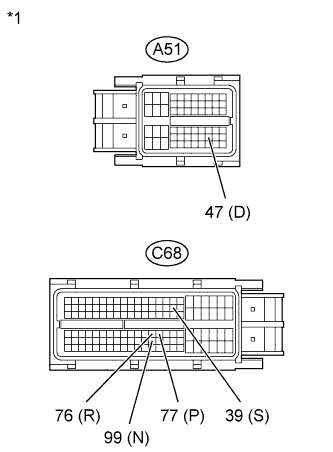
Text in Illustration *1 Front view of wire harness connector
(to ECM)
Disconnect the ECM connectors.
-
Measure the voltage according to the value(s) in the table below.
Standard Voltage Tester Connection Condition Specified Condition C68-77 (P) - Body ground
-
Ignition switch ON
-
Shift lever in P
11 to 14 V C68-76 (R) - Body ground
-
Ignition switch ON
-
Shift lever in R
11 to 14 V* C68-99 (N) - Body ground
-
Ignition switch ON
-
Shift lever in N
11 to 14 V A51-47 (D) - Body ground
-
Ignition switch ON
-
Shift lever in D
11 to 14 V C68-39 (S) - Body ground
-
Ignition switch ON
-
Shift lever in M, "+" or "-"
11 to 14 V C68-77 (P) - Body ground
-
Ignition switch ON
-
Shift lever not in P
Below 1 V C68-76 (R) - Body ground
-
Ignition switch ON
-
Shift lever not in R
Below 1 V C68-99 (N) - Body ground
-
Ignition switch ON
-
Shift lever not in N
Below 1 V A51-47 (D) - Body ground
-
Ignition switch ON
-
Shift lever not in D
Below 1 V C68-39 (S) - Body ground
-
Ignition switch ON
-
Shift lever not in M, "+" or "-"
Below 1 V Tech Tips
*: The voltage will drop slightly due to the illumination of the back-up light.
-
NG
REPAIR OR REPLACE HARNESS OR CONNECTOR
OK
-
-
REPLACE ECM
-
Replace the ECM Click here.
NEXT
-
-
PERFORM INITIALIZATION
Note
-
Performing reset memory will clear the learned values of both the yaw rate sensor (deceleration sensor 0 point calibration) and CVT oil pressure (CVT oil pressure calibration). Make sure to perform reset memory, yaw rate sensor 0 point calibration and CVT oil pressure calibration when replacing any of the parts shown in the following table:
Replaced Part
-
Continuously variable transaxle assembly
-
ECM
-
Oil pressure sensor
-
Yaw rate sensor
-
-
After performing reset memory, always perform yaw rate sensor (deceleration sensor 0 point) calibration first, and then CVT oil pressure calibration.
-
Always perform 0 point calibration with the vehicle on level ground (inclination: 0 +/-0.25°).
-
Do not shake or vibrate the vehicle during 0 point calibration.
-
Using the intelligent tester, perform reset memory, deceleration sensor 0 point calibration and CVT oil pressure calibration Click here.
-
Check that no DTC is stored.
NEXT 
END
-
-
CHECK HARNESS AND CONNECTOR (PARK/NEUTRAL POSITION SWITCH - ECM)
-
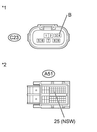
Text in Illustration *1 Front view of wire harness connector
(to Park/Neutral Position Switch)
*2 Front view of wire harness connector
(to ECM)
Disconnect the park/neutral position switch connector.
-
Disconnect the ECM connector.
-
Measure the resistance according to the value(s) in the table below.
Standard Resistance Tester Connection Condition Specified Condition C23-4 (B) - A51-25 (NSW) Always Below 1 Ω C23-4 (B) - Body ground Always 10 kΩ or higher A51-25 (NSW) - Body ground Always 10 kΩ or higher
NG
REPAIR OR REPLACE HARNESS OR CONNECTOR
OK
-
-
REPLACE ECM
-
Replace the ECM Click here.
NEXT
-
-
PERFORM INITIALIZATION
Note
-
Performing reset memory will clear the learned values of both the yaw rate sensor (deceleration sensor 0 point calibration) and CVT oil pressure (CVT oil pressure calibration). Make sure to perform reset memory, yaw rate sensor 0 point calibration and CVT oil pressure calibration when replacing any of the parts shown in the following table:
Replaced Part
-
Continuously variable transaxle assembly
-
ECM
-
Oil pressure sensor
-
Yaw rate sensor
-
-
After performing reset memory, always perform yaw rate sensor (deceleration sensor 0 point) calibration first, and then CVT oil pressure calibration.
-
Always perform 0 point calibration with the vehicle on level ground (inclination: 0 +/-0.25°).
-
Do not shake or vibrate the vehicle during 0 point calibration.
-
Using the intelligent tester, perform reset memory, deceleration sensor 0 point calibration and CVT oil pressure calibration Click here.
-
Check that no DTC is stored.
NEXT
END
-