- Click here
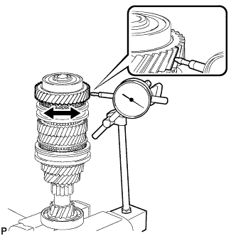
INSPECT 6TH GEAR THRUST CLEARANCE
-
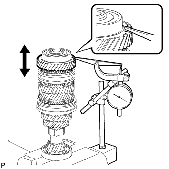
Using a dial indicator, measure the 6th gear thrust clearance.
Standard clearance 0.15 to 0.43 mm (0.00591 to 0.0169 in.) Maximum clearance 0.43 mm (0.0169 in.) If the clearance is more than the maximum, replace the No. 3 transmission clutch hub, 6th gear or input shaft. Replace the part or parts determined to be the most likely cause of the problem.
-
- Click here
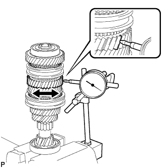
INSPECT 5TH GEAR THRUST CLEARANCE
-
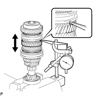
Using a dial indicator, measure the 5th gear thrust clearance.
Standard clearance 0.15 to 0.43 mm (0.00591 to 0.0169 in.) Maximum clearance 0.43 mm (0.0169 in.) If the clearance is more than the maximum, replace the No. 3 transmission clutch hub, 5th gear or input shaft. Replace the part or parts determined to be the most likely cause of the problem.
-
- Click here
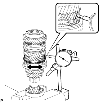
INSPECT 4TH GEAR THRUST CLEARANCE
-
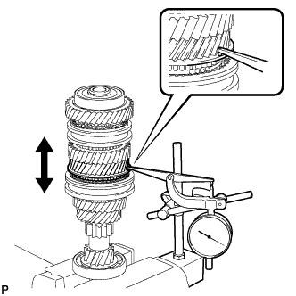
Using a dial indicator, measure the 4th gear thrust clearance.
Standard clearance 0.15 to 0.56 mm (0.00591 to 0.0220 in.) Maximum clearance 0.56 mm (0.0220 in.) If the clearance is more than the maximum, replace the No. 2 transmission clutch hub, 4th gear or input shaft. Replace the part or parts determined to be the most likely cause of the problem.
-
- Click here
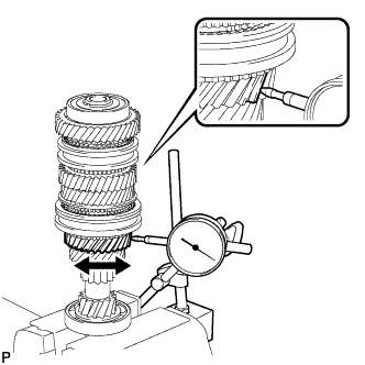
INSPECT 3RD GEAR THRUST CLEARANCE
-
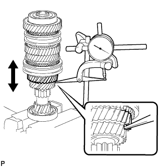
Using a dial indicator, measure the 3rd gear thrust clearance.
Standard clearance 0.15 to 0.43 mm (0.00591 to 0.0169 in.) Maximum clearance 0.43 mm (0.0169 in.) If the clearance is more than the maximum, replace the No. 2 transmission clutch hub, 3rd gear or input shaft. Replace the part or parts determined to be the most likely cause of the problem.
-
- Click here
INSPECT 6TH GEAR RADIAL CLEARANCE
-
Using a dial indicator, measure the 6th gear radial clearance between the gear and shaft.
Standard clearance 0.009 to 0.045 mm (0.000354 to 0.00177 in.) Maximum clearance 0.045 mm (0.00177 in.) If the clearance is more than the maximum, replace the 6th gear, 6th gear needle roller bearing, inner 6th gear bearing race or input shaft. Replace the part or parts determined to be the most likely cause of the problem.
-
- Click here
INSPECT 5TH GEAR RADIAL CLEARANCE
-
Using a dial indicator, measure the 5th gear radial clearance between the gear and shaft.
Standard clearance 0.009 to 0.045 mm (0.000354 to 0.00177 in.) Maximum clearance 0.045 mm (0.00177 in.) If the clearance is more than the maximum, replace the 5th gear, 5th gear needle roller bearing, inner 5th gear bearing race or input shaft. Replace the part or parts determined to be the most likely cause of the problem.
-
- Click here
INSPECT 4TH GEAR RADIAL CLEARANCE
-
Using a dial indicator, measure the 4th gear radial clearance between the gear and shaft.
Standard clearance 0.009 to 0.050 mm (0.000354 to 0.0197 in.) Maximum clearance 0.050 mm (0.0197 in.) If the clearance is more than the maximum, replace the 4th gear, 4th gear needle roller bearing or input shaft. Replace the part or parts determined to be the most likely cause of the problem.
-
- Click here
INSPECT 3RD GEAR RADIAL CLEARANCE
-
Using a dial indicator, measure the 3rd gear radial clearance.
Standard clearance 0.009 to 0.050 mm (0.000354 to 0.0197 in.) Maximum clearance 0.050 mm (0.0197 in.) If the clearance is more than the maximum, replace the 3rd gear, 3rd gear needle roller bearing or input shaft. Replace the part or parts determined to be the most likely cause of the problem.
-
- Click here
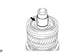
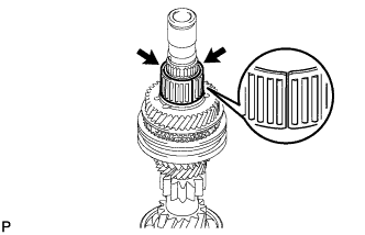
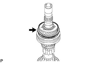
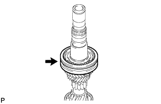
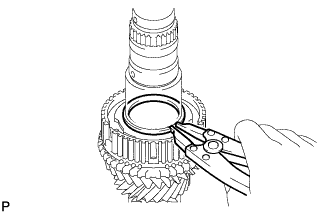
REMOVE REAR INPUT SHAFT BEARING SHAFT SNAP RING
-
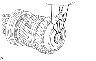
Using a snap ring expander, remove the rear input shaft bearing shaft snap ring.
-
- Click here
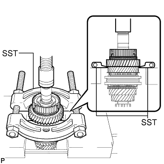
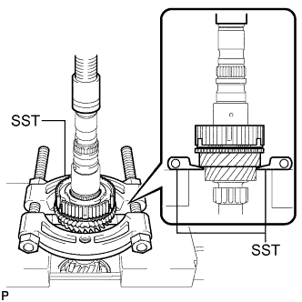
REMOVE 6TH GEAR SUB-ASSEMBLY
-
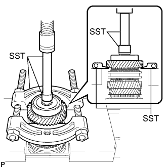
Using SST and a press, remove the rear input shaft radial ball bearing and 6th gear from the input shaft.
09950-00020 09950-60010 09951-00270 09950-70010 09951-07100 Note:
-
Do not tighten SST excessively.
-
Support the input shaft by hand to prevent it from falling.
-
-
- Click here
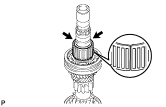
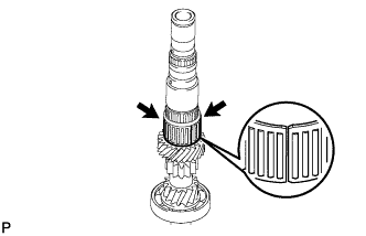
REMOVE 6TH GEAR NEEDLE ROLLER BEARING
-
Remove the 2 pieces of the 6th gear needle roller bearing from the inner 6th gear bearing race.
-
- Click here
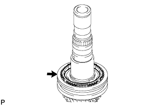
REMOVE NO. 5 SYNCHRONIZER RING
-
Remove the No. 5 synchronizer ring from the No. 3 transmission clutch hub.
-
- Click here
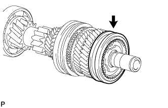
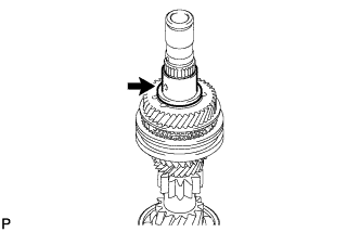
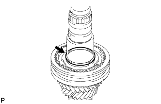
REMOVE INNER 6TH GEAR BEARING RACE
-
Remove the inner 6th gear bearing race from the input shaft.
-
- Click here
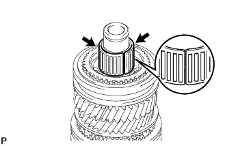
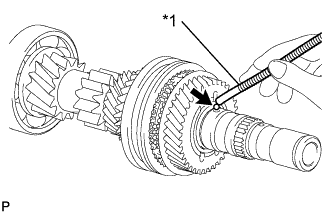
REMOVE INNER 6TH GEAR BEARING RACE LOCK BALL
-
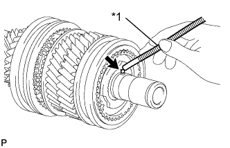
Using a magnet hand, remove the inner 6th gear bearing race lock ball from the input shaft.
Table 1. Text in Illustration *1 Magnet Hand
-
- Click here
REMOVE NO. 3 TRANSMISSION HUB SLEEVE
-
Remove the No. 3 transmission hub sleeve from the No. 3 transmission clutch hub.
-
- Click here
REMOVE NO. 3 SYNCHROMESH SHIFTING KEY
-
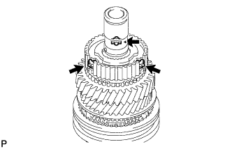
Remove the 3 No. 3 synchromesh shifting keys from the No. 3 transmission clutch hub.
-
- Click here
REMOVE 5TH GEAR
-
Using SST and a press, remove the No. 3 transmission clutch hub, No. 5 synchronizer ring and 5th gear from the input shaft.
09950-00020 Note:
-
Do not tighten SST excessively.
-
Support the input shaft by hand to prevent it from falling.
-
-
- Click here
REMOVE 5TH GEAR NEEDLE ROLLER BEARING
-
Remove the 2 pieces of the 5th gear needle roller bearing from the inner 5th gear bearing race.
-
- Click here
REMOVE INNER 5TH GEAR BEARING RACE
-
Remove the inner 5th gear bearing race from the input shaft.
-
- Click here
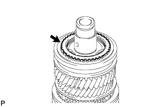
REMOVE INNER 5TH GEAR BEARING RACE LOCK BALL
-
Using a magnet hand, remove the inner 5th gear bearing race lock ball from the input shaft.
Table 2. Text in Illustration *1 Magnet Hand
-
- Click here
REMOVE 4TH GEAR
-
Remove the 4th gear from the input shaft.
-
- Click here
REMOVE 4TH GEAR NEEDLE ROLLER BEARING
-
Remove the 2 pieces of the 4th gear needle roller bearing from the input shaft.
-
- Click here
REMOVE OUTER 2ND SYNCHRONIZER RING
-
Remove the outer 2nd synchronizer ring from the No. 2 transmission clutch hub.
-
- Click here
REMOVE 4TH GEAR BEARING SPACER
-
Remove the 4th gear bearing spacer from the No. 2 transmission clutch hub.
-
- Click here
REMOVE NO. 2 TRANSMISSION HUB SLEEVE
-
Remove the No. 2 transmission hub sleeve from the No. 2 transmission clutch hub.
-
- Click here
REMOVE NO. 2 SYNCHROMESH SHIFTING KEY
-
Remove the 3 No. 2 synchromesh shifting keys from the No. 2 transmission clutch hub.
-
- Click here
REMOVE NO. 2 CLUTCH HUB SETTING SHAFT SNAP RING
-
Using a snap ring expander, remove the No. 2 clutch hub setting shaft snap ring.
-
- Click here
REMOVE 3RD GEAR
-
Using SST and a press, remove the No. 2 transmission clutch hub, No. 3 synchronizer ring and 3rd gear from the input shaft.
09950-00020 Note:
-
Do not tighten SST excessively.
-
Support the input shaft by hand to prevent it from falling.
-
-
- Click here
REMOVE 3RD GEAR NEEDLE ROLLER BEARING
-
Remove the 2 pieces of the 3rd gear needle roller bearing from the input shaft.
-
- Click here
REMOVE FRONT INPUT SHAFT BEARING
-
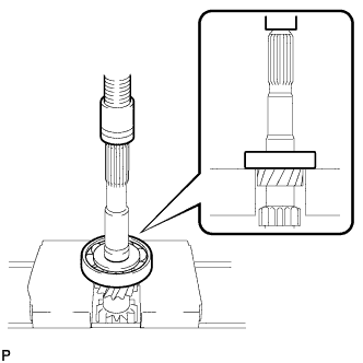
Using a press, press out the front input shaft bearing from the input shaft.
Note:Support the input shaft by hand to prevent it from falling.
-