Click here
-
ECM
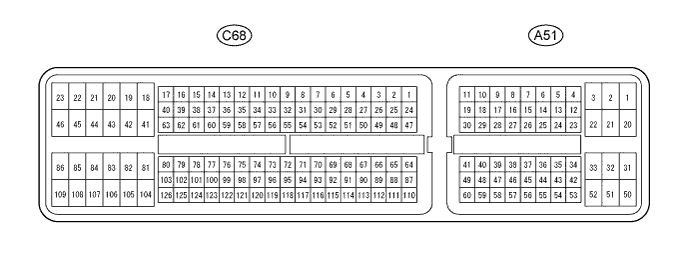
Tip:The standard voltage and resistance of each ECM terminal is shown in the table below.
In the table, first follow the information under "Condition". Look under "Terminal No. (Symbol)" for the terminals to be inspected. The standard voltage or resistance between the terminals is shown under "Specified Condition".
Use the illustration above as a reference for the ECM terminals.
Terminal No. (Symbol) Wiring Color Terminal Description Condition Specified Condition A51-1 (+B2) - C68-105 (E1) B - BR Power source of ECM Ignition switch ON 11 to 14 V A51-2 (+B) - C68-105 (E1) B - BR Power source of ECM Ignition switch ON 11 to 14 V A51-3 (+BM) - C68-105 (E1) B - BR Power source of throttle actuator Always 11 to 14 V A51-8 (CANH) - C68-105 (E1) Y - BR CAN communication line Ignition switch ON Pulse generation
(See waveform 1)
A51-9 (CANL) - C68-105 (E1) W - BR CAN communication line Ignition switch ON Pulse generation
(See waveform 2)
A51-16 (SFTU) - C68-105 (E1) W - BR Up-shift position switch signal Ignition switch ON and shift lever in M 11 to 14 V
-
Ignition switch ON and shift lever in "+" (up-shift)
-
Ignition switch ON and "+" shift paddle operated (up-shift)
Below 1 V A51-17 (PWMS) - C68-105 (E1) R - BR No. 1 pattern select switch (SPORT) signal Ignition switch ON and No. 1 pattern select switch (SPORT) off 11 to 14 V Ignition switch ON and No. 1 pattern select switch (SPORT) on Below 1.5 V A51-20 (BATT) - C68-105 (E1) P - BR Battery (for measuring battery voltage and for ECM memory) Always 11 to 14 V A51-25 (NSW) - C68-105 (E1) G - BR Park/neutral position switch signal Ignition switch ON and shift lever in P or N Below 1 V Ignition switch ON and shift lever not in P or N 11 to 14 V A51-36 (STP) - C68-105 (E1) V - BR Stop light switch signal Brake pedal depressed 11 to 14 V Brake pedal released Below 1.5 V A51-44 (MREL) - C68-105 (E1) L - BR EFI MAIN relay Ignition switch ON 11 to 14 V A51-47 (D) - C68-105 (E1) G - BR D position switch signal Ignition switch ON and shift lever in D 11 to 14 V Ignition switch ON and shift lever not in D Below 1 V A51-48 (STA) - C68-105 (E1) LG - BR Starter signal Cranking 5.5 V or higher A51-51 (SFTD) - C68-105 (E1) R - BR Down-shift position switch signal Ignition switch ON and shift lever in M 11 to 14 V
-
Ignition switch ON and shift lever in "-" (down-shift)
-
Ignition switch ON and "-" shift paddle operated (down-shift)
Below 1 V C68-39 (S) - C68-105 (E1) L - BR M position switch signal Ignition switch ON and shift lever in M 11 to 14 V Ignition switch ON and shift lever not in M Below 1 V C68-54 (SLS+) - C68-53 (SLS-) L - P Shift solenoid valve SLS signal Engine idling Pulse generation
(See waveform 3)
C68-55 (DS2) - C68-105 (E1) R - BR Shift solenoid valve DS2 signal Accelerator pedal depressed further after driving at constant vehicle speed with shift lever in D Pulse generation
(See waveform 4)
C68-56 (DS1) - C68-105 (E1) V - BR Shift solenoid valve DS1 signal Accelerator pedal released while driving with shift lever in D Pulse generation
(See waveform 5)
C68-59 (DSU) - C68-105 (E1) B - BR Shift solenoid valve DSU signal Lock-up turned from off to on Pulse generation
(See waveform 6)
C68-61 (SLT+) - C68-60 (SLT-) LG - G Shift solenoid valve SLT signal Engine idling Pulse generation
(See waveform 7)
C68-70 (THO1) - C68-71 (ETHO) Y - R CVT fluid temperature sensor signal CVT fluid temperature: 60 to 120°C (140 to 248°F) 0.2 to 1.0 V C68-73 (PTO) - C68-72 (EPTO) W - B Oil pressure sensor signal Engine idling speed and shift lever in P 0.8 to 1.2 V C68-76 (R) - C68-105 (E1) R - BR R position switch signal Ignition switch ON and shift lever in R 11 to 14 V Ignition switch ON and shift lever not in R Below 1 V C68-77 (P) - C68-105 (E1) V - BR P position switch signal Ignition switch ON and shift lever in P 11 to 14 V Ignition switch ON and shift lever not in P Below 1 V C68-95 (VCPT) - C68-72 (EPTO) P - B Power supply for oil pressure sensor signal Ignition switch ON 4.5 to 5.5 V C68-99 (N) - C68-105 (E1) B - BR N position switch signal Ignition switch ON and shift lever in N 11 to 14 V Ignition switch ON and shift lever not in N Below 1 V C68-105 (E1) - Body ground BR - Body ground Ground Always Below 1 Ω C68-122 (NIN+) - C68-100 (NIN-) LG - L Transmission revolution sensor (NIN) signal Vehicle is driven with shift lever in D, vehicle speed approx. 6 km/h (3.7 mph) and engine speed approx. 760 rpm Pulse generation
(See waveform 8)
C68-124 (NTO) - C68-123 (NTB) B - Y Transmission revolution sensor (NT) signal Vehicle is driven with shift lever in D, vehicle speed approx. 12 km/h (7.5 mph) and engine speed approx. 1000 rpm Pulse generation
(See waveform 9)
C68-125 (NOTO) - C68-101 (NOTB) L - R Transmission revolution sensor (NOUT) signal Vehicle is driven with shift lever in D, vehicle speed approx. 12 km/h (7.5 mph) and engine speed approx. 1000 rpm Pulse generation
(See waveform 10)
-
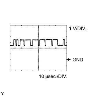
Using an oscilloscope, check waveform 1.
Table 1. Waveform 1 (reference) Terminal No. (Symbol) Tool Setting Condition A51-8 (CANH) - C68-105 (E1) 1 V/DIV., 10 μsec./DIV. Ignition switch ON -
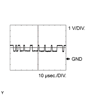
Using an oscilloscope, check waveform 2.
Table 2. Waveform 2 (reference) Terminal No. (Symbol) Tool Setting Condition A51-9 (CANL) - C68-105 (E1) 1 V/DIV., 10 μsec./DIV. Ignition switch ON -
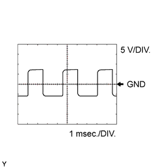
Using an oscilloscope, check waveform 3.
Table 3. Waveform 3 (reference) Terminal No. (Symbol) Tool Setting Condition C68-54 (SLS+) - C68-53 (SLS-) 5 V/DIV., 1 msec./DIV. Engine idling -
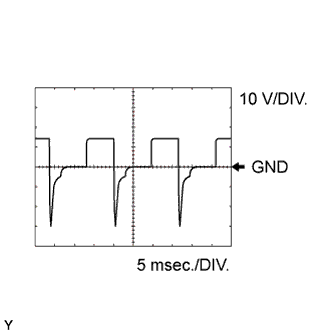
Using an oscilloscope, check waveform 4.
Table 4. Waveform 4 (reference) Terminal No. (Symbol) Tool Setting Condition C68-55 (DS2) - C68-105 (E1) 10 V/DIV., 5 msec./DIV. Accelerator pedal depressed further after driving at constant vehicle speed with shift lever in D Tip:Duty ratio increases as the gear ratio increases.
-
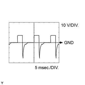
Using an oscilloscope, check waveform 5.
Table 5. Waveform 5 (reference) Terminal No. (Symbol) Tool Setting Condition C68-56 (DS1) - C68-105 (E1) 10 V/DIV., 5 msec./DIV. Accelerator pedal released while driving with shift lever in D Tip:Duty ratio increases as the gear ratio decreases.
-
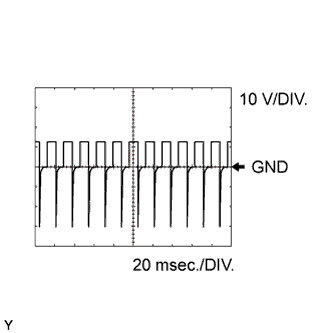
Using an oscilloscope, check waveform 6.
Table 6. Waveform 6 (reference) Terminal No. (Symbol) Tool Setting Condition C68-59 (DSU) - C68-105 (E1) 10 V/DIV., 20 msec./DIV. Lock-up turned from off to on Tip:Duty ratio increases to 100% with lock-up on.
-
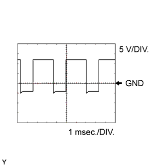
Using an oscilloscope, check waveform 7.
Table 7. Waveform 7 (reference) Terminal No. (Symbol) Tool Setting Condition C68-61 (SLT+) - C68-60 (SLT-) 5 V/DIV., 1 msec./DIV. Engine idling Tip:Duty ratio increases to 100% with the lock up ON.
-
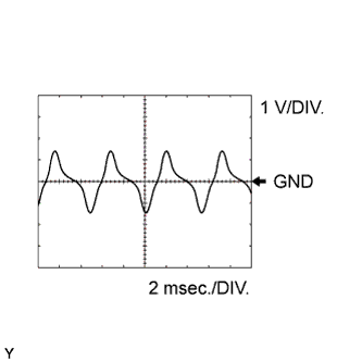
Using an oscilloscope, check waveform 8.
Table 8. Waveform 8 (reference) Terminal No. (Symbol) Tool Setting Condition C68-122 (NIN+) - C68-100 (NIN-) 1 V/DIV., 2 msec./DIV. Vehicle is driven with shift lever in D, vehicle speed approx. 6 km/h (3.7 mph) and engine speed approx. 760 rpm Tip:The wavelength shortens and the voltage increases as the primary pulley speed increases.
-
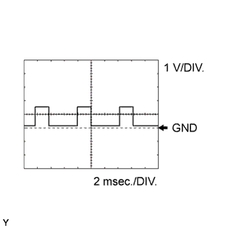
Using an oscilloscope, check waveform 9.
Table 9. Waveform 9 (reference) Terminal No. (Symbol) Tool Setting Condition C68-124 (NTO) - C68-123 (NTB) 1 V/DIV., 2 msec./DIV. Vehicle is driven with shift lever in D, vehicle speed approx. 12 km/h (7.5 mph) and engine speed approx. 1000 rpm Tip:The wavelength shortens as the turbine speed increases.
-
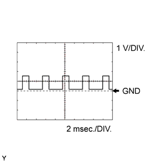
Using an oscilloscope, check waveform 10.
Table 10. Waveform 10 (reference) Terminal No. (Symbol) Tool Setting Condition C68-125 (NOTO) - C68-101 (NOTB) 1 V/DIV., 2 msec./DIV. Vehicle is driven with shift lever in D, vehicle speed approx. 12 km/h (7.5 mph) and engine speed approx. 1000 rpm Tip:The wavelength shortens as the secondary pulley speed increases.
-