DIFFERENTIAL CASE DISASSEMBLY

-
INSPECT FRONT DIFFERENTIAL CASE ASSEMBLY WITH RING GEAR
-
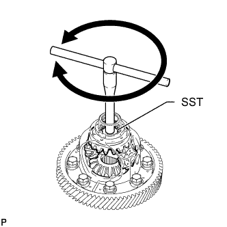
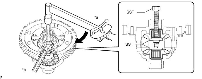
Using SST, rotate the front differential side gear as shown in the illustration.
- SST
- 09528-52010 ( 09528-05040 )
Standard The front differential side gear does not lock when rotated in either direction.
-
If the front differential side gear locks, perform all inspections.
-
If the front differential side gear still locks even after replacing the malfunctioning parts, replace the front differential case assembly with ring gear.
-
-
INSPECT FRONT DIFFERENTIAL SIDE GEAR THRUST AMOUNT
-
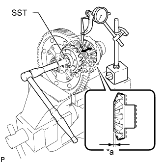
Text in Illustration *a Front Differential Side Gear Thrust Amount Using SST and a dial indicator, measure the front differential side gear thrust amount.
- SST
- 09528-52010 ( 09528-05040 )
Front differential side gear thrust amount 0.08 mm (0.00315 in.) or less Tech Tips
-
Measure the front differential side gear thrust amount while slowly rotating the front differential side gear.
-
Make sure to measure the front differential side gear thrust amount for both of the 2 front differential side gears.
If the result is not as specified, replace the 2 front differential side gears, 2 front differential pinions, 2 front differential pinion thrust washers and 2 conical springs.
-
-
REMOVE FRONT DIFFERENTIAL PINION SHAFT STRAIGHT PIN
-
Mount the front differential case in a vise between aluminum plates.
Note
Do not overtighten the vise.
-
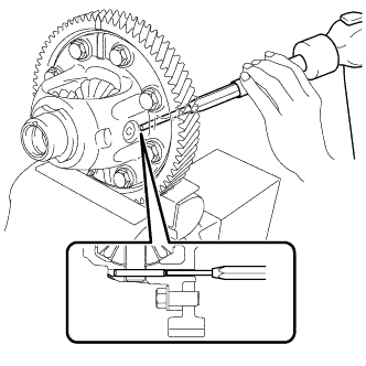
Using a 5 mm pin punch and hammer, remove the front differential pinion shaft straight pin from the front differential case assembly with ring gear.
-
-
REMOVE FRONT NO. 1 DIFFERENTIAL PINION SHAFT
-
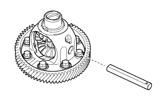
Remove the front No. 1 differential pinion shaft from the front differential case assembly with ring gear.
-
-
INSPECT FRONT DIFFERENTIAL PINION BACKLASH
-
Install SST as shown in the illustration and tighten it.
- SST
- 09528-52010 ( 09528-05020, 09953-05010 )
- Torque:
- 10 N*m { 102 kgf*cm, 7 ft.*lbf }
Text in Illustration *a Turn *b Hold -
Secure the front differential case assembly with ring gear in a vise between aluminum plates.
Note
Do not overtighten the vise.
-
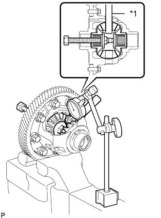
Text in Illustration *1 Front No. 1 Differential Pinion Shaft Install the front No. 1 differential pinion shaft to the front differential pinion as shown in the illustration.
-
Using a dial indicator, measure the front differential pinion backlash.
Standard backlash 0.20 mm (0.00787 in.) or less If the backlash is not as specified, replace the front No. 1 differential side gear thrust washers with washers of a different thickness. Use the table below to select a front No. 1 differential side gear thrust washer which will ensure that the backlash is within the specification.
Front No. 1 Differential Side Gear Thrust Washer Thickness Mark Specified Condition 19 0.90 mm (0.0354 in.) 14 0.95 mm (0.0374 in.) 02 1.00 mm (0.0394 in.) 15 1.05 mm (0.0413 in.) 03 1.10 mm (0.0433 in.) 16 1.15 mm (0.0453 in.) 04 1.20 mm (0.0472 in.) Tech Tips
Select front No. 1 differential side gear thrust washers of the same thickness for both the right and left side.
-
-
REMOVE FRONT DIFFERENTIAL SIDE GEAR
-
Install SST as shown in the illustration and tighten it.
- SST
- 09528-52010 ( 09528-05020, 09953-05010 )
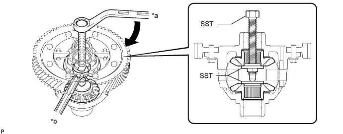
Text in Illustration *a Turn *b Hold Note
Do not overtighten SST, as doing so will damage the front differential side gears, conical springs, front No. 1 differential side gear thrust washers and front differential case assembly with ring gear.
Tech Tips
-
Tighten SST until there is clearance between the front differential pinions and front differential side gears.
-
When removing the front differential pinions, do not overtighten SST, as it is necessary to rotate the front differential side gears.
-
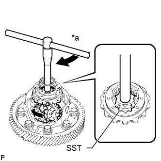
Text in Illustration *a Turn Install SST as shown in the illustration, rotate the front differential side gear, and then remove the 2 front differential pinions and 2 front differential pinion thrust washers from the front differential case assembly with ring gear.
- SST
- 09528-52010 ( 09528-05040 )
Note
Do not drop the differential pinion and front differential pinion thrust washer.
-
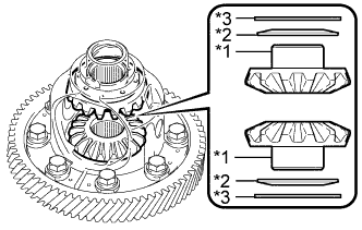
Text in Illustration *1 Front Differential Side Gear *2 Conical Spring *3 Front No. 1 Differential Side Gear Thrust Washer Remove SST from the front differential case assembly with ring gear, and then remove the 2 front differential side gears, 2 front No. 1 differential side gear thrust washers and 2 conical springs from the front differential case assembly with ring gear.
Note
Do not drop the front differential side gear, front No. 1 differential side gear thrust washer and conical spring.
-