MANUAL TRANSAXLE ASSEMBLY REMOVAL

Note
When the transaxle is removed, be sure to use a new clutch release with bearing cylinder and new installation bolts. Removal of the transaxle allows the compressed clutch release with bearing cylinder to return to its original position, and dust could damage the seal of the clutch release with bearing cylinder, possibly causing clutch fluid leaks.
-
REMOVE ENGINE ASSEMBLY WITH TRANSAXLE
-
Remove the engine assembly with transaxle Click here.
-
-
REMOVE STARTER ASSEMBLY
-
Remove the starter assembly Click here.
-
-
REMOVE ENGINE WIRE
-
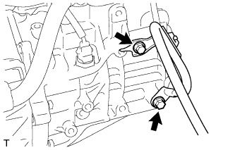
Remove the 2 bolts and engine wire.
-
-
REMOVE MANUAL TRANSAXLE ASSEMBLY
-
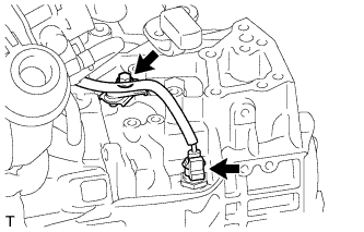
Disconnect the back-up light switch connector and remove the bolt and wire harness from the manual transaxle.
-
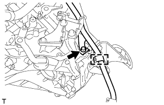
Remove the bolt, clamp and wire harness from the manual transaxle.
-
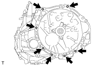
Remove the 7 bolts and manual transaxle.
-
-
REMOVE FRONT ENGINE MOUNTING BRACKET
-
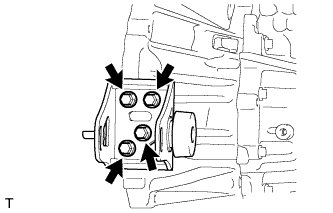
Remove the 4 bolts and front engine mounting bracket.
-
-
REMOVE ENGINE MOUNTING BRACKET LH
-
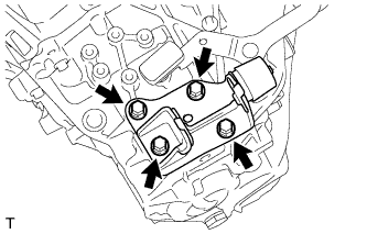
Remove the 4 bolts and engine mounting bracket LH.
-
-
REMOVE REAR ENGINE MOUNTING BRACKET
-
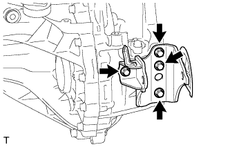
Remove the 4 bolts and rear engine mounting bracket.
-
-
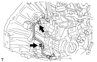
REMOVE CLUTCH RELEASE BLEEDER TO FLEXIBLE HOSE TUBE
-
Remove the bolt and disconnect the clamp.
-
Using a union nut wrench, remove the clutch release bleeder to flexible hose tube from the clutch release bleeder sub-assembly.
-
-
REMOVE CLUTCH FLEXIBLE HOSE BRACKET
-
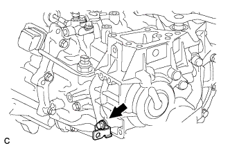
Remove the bolt and clutch flexible hose bracket from the manual transaxle.
-
-
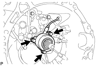
REMOVE CLUTCH RELEASE BLEEDER SUB-ASSEMBLY
-
Using a union nut wrench, separate the clutch release bleeder sub-assembly from the clutch release cylinder to bleeder tube.
-
Remove the 2 bolts and clutch release bleeder sub-assembly from the manual transaxle assembly.
-
-
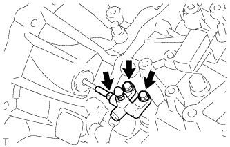
REMOVE CLUTCH RELEASE WITH BEARING CYLINDER ASSEMBLY
-
Remove the clutch tube boot from the manual transaxle assembly.
-
Remove the 3 bolts and clutch release with bearing cylinder assembly together with the clutch release cylinder to bleeder tube.
-
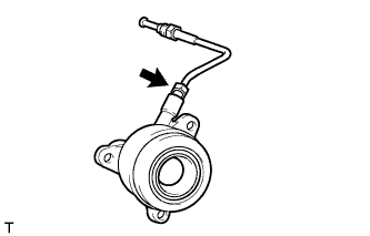
Using a union nut wrench, remove the clutch release cylinder to bleeder tube from the clutch release with bearing cylinder assembly.
-
-
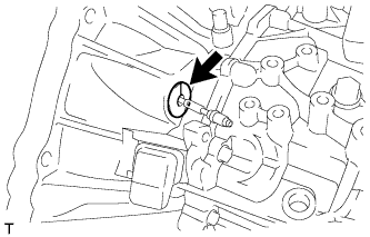
REMOVE SPEEDOMETER DRIVEN HOLE COVER SUB-ASSEMBLY
-
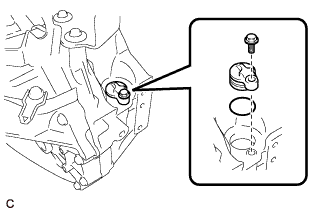
Remove the bolt and speedometer driven hole cover sub-assembly from the transaxle case.
-
Remove the O-ring from the speedometer driven hole cover sub-assembly.
-