TRANSMISSION CONTROL CABLE INSTALLATION

-
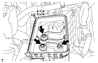
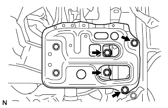
INSTALL TRANSMISSION CONTROL CABLE ASSEMBLY
-
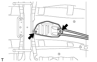
Attach the grommet of the control cable assembly with the 2 nuts.
- Torque:
- 5.0 N*m { 51 kgf*cm, 44 in.*lbf }
-
Attach the bracket of the control cable assembly with the bolt.
- Torque:
- 5.0 N*m { 51 kgf*cm, 44 in.*lbf }
-
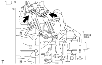
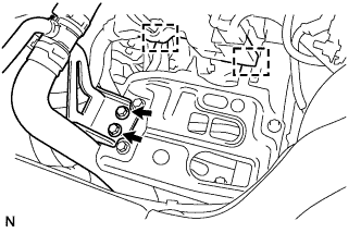
Connect the 2 cables to the control cable bracket with 2 new clips.
-
Connect the 2 cables to the transaxle and install the 2 clips.
-
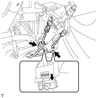
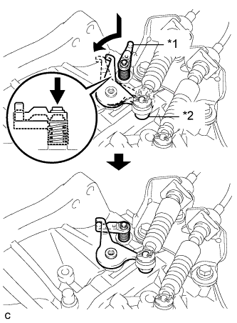
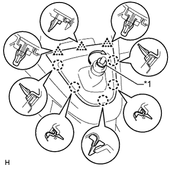
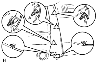
Engage the 2 claws, and install the control cable assembly to the shift lever assembly.
Note
Make sure that the claws are firmly engaged.
-
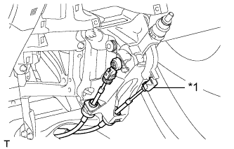
Text in Illustration *1 Select Cable Install the control shift cable to the shift lever assembly.
-
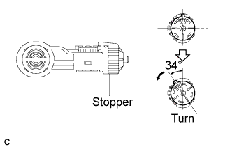
Release the lock of the cable length adjustment structure of the select cable.
-
Turn the stopper.
-

Pull the lock piece outward from the case to release the lock.
-
Return the stopper.
-
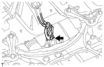
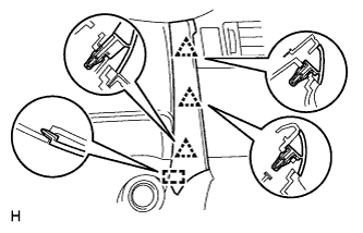
-
Text in Illustration *1 Reverse Restrict Pin Assembly *2 Outer Lever Hook the outer lever of the manual transaxle onto the reverse restrict pin assembly to secure it.
-
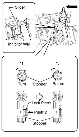
Connect the control select cable to the shift lever assembly.
-
Push the slider against the inhibitor wall.
Note
-
Do not pull up the slider.
-
When adjusting the cable, make sure that the shift lever is not in the 1 or 2.
-
-
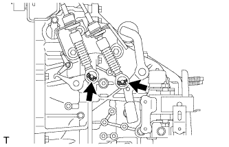
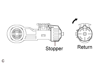
Lock the cable length adjustment structure of the select cable.
-
Turn the stopper.*1
-
Push the lock piece into the case.*2
-
Return the stopper to prevent the lock from being released.*3
Note
-
Push the lock piece as far as it will go.
-
Confirm whether the cable length adjustment structure is locked securely.
-
-
-
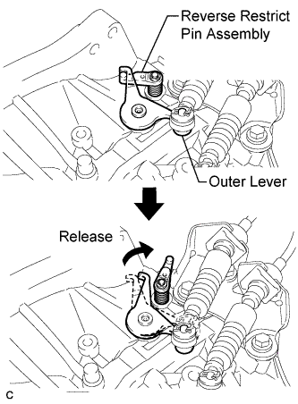
Move the shift lever to R to release the outer lever.
-
-
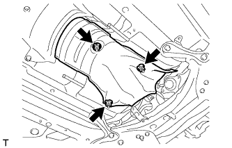
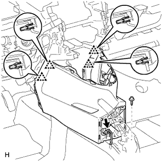
INSTALL FRONT NO. 1 FLOOR HEAT INSULATOR
-
Install the front No. 1 floor heat insulator with the 3 nuts.
- Torque:
- 5.5 N*m { 56 kgf*cm, 49 in.*lbf }
-
-
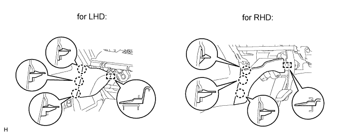
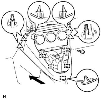
INSTALL LOWER NO. 1 INSTRUMENT PANEL FINISH PANEL
-
Attach the 4 clips to install the lower No. 1 instrument panel finish panel.
-
Connect the connector.
-
Install the screw <D>.
-
-
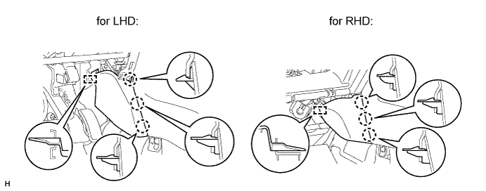
INSTALL FRONT NO. 2 CONSOLE BOX INSERT
-
Attach the 3 claws and guide to install the front No. 2 console box insert.
-
-
INSTALL FRONT NO. 1 CONSOLE BOX INSERT
-
Attach the 3 claws and guide to install the front No. 1 console box insert.
-
-
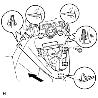
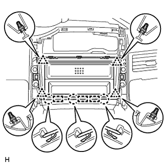
INSTALL LOWER CENTER INSTRUMENT PANEL FINISH PANEL
-
for Automatic Air Conditioning System:
-
Attach the 2 claws, 4 clips and 5 guides to install the lower center instrument panel finish panel.
-
Install the 2 screws <C>.
-
-
for Manual Air Conditioning System:
-
Attach the 4 clips, 2 claws and 5 guides to install the lower center instrument panel finish panel.
-
Install the 2 screws <C>.
-
-
-
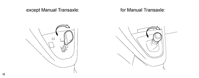
INSTALL SHIFTING HOLE COVER
Text in Illustration *1 T Washer
-
Attach the 5 claws and 3 clips to install the shifting hole cover.
-
Install the knob spring.
-
Install the T washer and twist it in the direction indicated by the arrow.
-
-
INSTALL SHIFT LEVER KNOB SUB-ASSEMBLY
-
Install the shift lever knob and twist it in the direction indicated by the arrow.
-
-
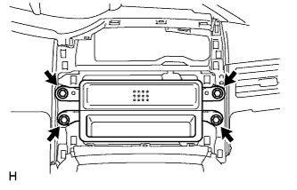
INSTALL STEREO OPENING COVER WITH BRACKET (w/o Audio)
-
Install the stereo opening cover with the 4 bolts.
-
-
INSTALL CENTER INSTRUMENT CLUSTER FINISH PANEL SUB-ASSEMBLY (w/o Audio)
-
Attach the 4 clips, 3 claws and 3 guides to install the center instrument cluster finish panel.
-
-
INSTALL RADIO RECEIVER ASSEMBLY (w/ Audio)
-
for Radio Receiver Type:
Install the radio receiver assembly Click here.
-
for Radio and Display Type:
Install the radio receiver assembly Click here.
-
-
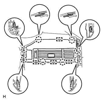
INSTALL CENTER INSTRUMENT PANEL REGISTER ASSEMBLY
-
Connect the connector.
-
Attach the 8 claws and 4 guides to install the center instrument panel register.
-
-
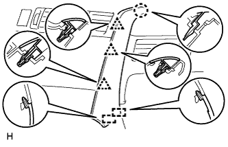
INSTALL INSTRUMENT PANEL FINISH PANEL END RH
-
for Automatic Air Conditioning System:
Attach the 3 clips, claw and 2 guides to install the instrument panel finish panel end.
-
for Manual Air Conditioning System:
Attach the 3 clips, claw and guide to install the instrument panel finish panel end.
-
-
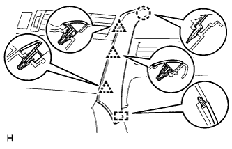
INSTALL INSTRUMENT PANEL FINISH PANEL END LH
-
for Automatic Air Conditioning System:
Attach the 3 clips and 2 guides to install the instrument panel finish panel end.
-
for Manual Air Conditioning System:
Attach the 3 clips and guide to install the instrument panel finish panel end.
-
-
INSTALL BOX PANEL SUB-ASSEMBLY
-
Install the box panel sub-assembly Click here.
-
-
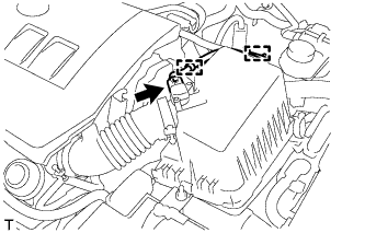
INSTALL AIR CLEANER CASE
-
Install the air cleaner case with the 3 bolts.
- Torque:
- 7.0 N*m { 71 kgf*cm, 62 in.*lbf }
-
Attach the wire harness clamp to the air cleaner case.
-
-
INSTALL AIR CLEANER CAP SUB-ASSEMBLY
-
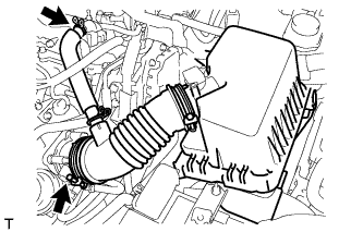
Connect the air cleaner cap with the band.
-
Connect the PCV hose.
-
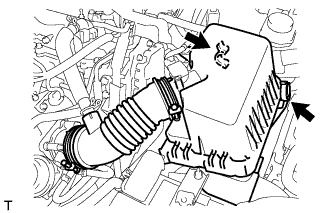
Connect the 2 clamps.
-
Attach the 2 clamps and connect the wire harness.
-
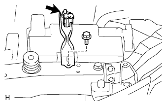
Connect the mass air flow meter connector.
-
-
INSTALL BATTERY CARRIER
-
Install the battery carrier with the 4 bolts.
- Torque:
- 19 N*m { 189 kgf*cm, 14 ft.*lbf }
-
Install the radiator pipe with the 2 bolts.
- Torque:
- 19 N*m { 189 kgf*cm, 14 ft.*lbf }
-
Connect the 2 wire harness clamps.
-
-
INSTALL BATTERY TRAY
-
INSTALL BATTERY
-
INSTALL BATTERY CLAMP SUB-ASSEMBLY
-
Install the battery clamp with the bolt and nut.
- Torque:
- for bolt
- 17 N*m { 169 kgf*cm, 12 ft.*lbf }
- for nut
- 3.5 N*m { 36 kgf*cm, 31 in.*lbf }
-
Connect the cable to the positive (+) battery terminal.
- Torque:
- 5.4 N*m { 55 kgf*cm, 48 in.*lbf }
-
-
INSTALL RADIATOR SUPPORT OPENING COVER
-
Attach the 4 hooks to install the radiator support opening cover.
-
Install the 5 clips.
-
-
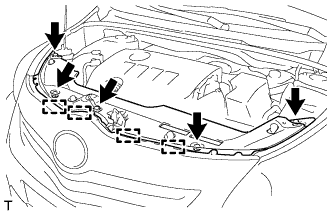
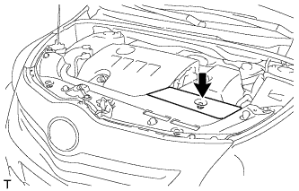
INSTALL NO. 2 CYLINDER HEAD COVER
-
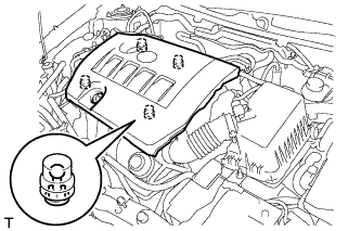
Attach the 4 clips to install the cover.
Note
-
Be sure to attach the clips securely.
-
Do not apply excessive force or hit the cover to attach the clips. This may cause the cover to break.
-
-
-
CONNECT CABLE TO POSITIVE BATTERY TERMINAL
-
CONNECT CABLE TO NEGATIVE BATTERY TERMINAL
Note
When disconnecting the cable, some systems need to be initialized after the cable is reconnected Click here.
-
INSTALL BATTERY SERVICE HOLE COVER
-
Install the battery service hole cover with the clip.
-
-
INSTALL FRONT EXHAUST PIPE ASSEMBLY
-
Install the front exhaust pipe assembly Click here.
-