TRANSMISSION CONTROL CABLE (for 1WW) INSTALLATION

-
INSTALL TRANSMISSION CONTROL CABLE ASSEMBLY
-
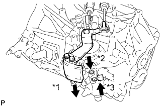
Attach the grommet of the transmission control cable assembly with the 2 nuts.
- Torque:
- 5.0 N*m { 51 kgf*cm, 44 in.*lbf }
-
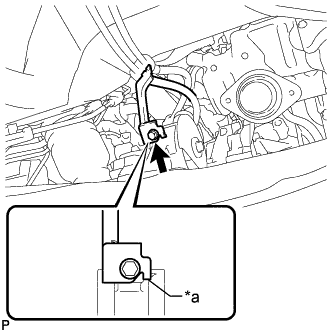
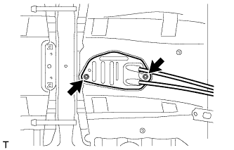
Text in Illustration *a Anti-rotation pin Attach the bracket of the transmission control cable assembly with the bolt.
- Torque:
- 5.0 N*m { 51 kgf*cm, 44 in.*lbf }
Tech Tips
Make sure the anti-rotation pin is contacting the rear engine mount insulator.
-
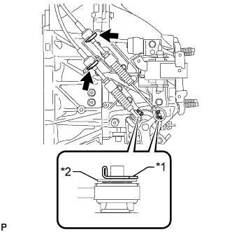
Text in Illustration *1 Clip *2 Metal Washer Plate Connect the 2 cables to the control cable bracket with 2 new clips.
Note
Do not bend the cable more than necessary.
-
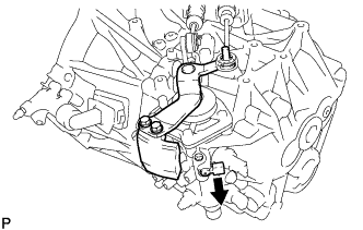
Connect the 2 cables to the manual transaxle assembly and install the 2 clips.
Tech Tips
Make sure that the metal washer plate of the shift cable is facing toward the outside of the vehicle.
-
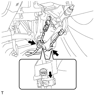
Engage the 2 claws, and install the transmission control cable assembly to the shift lever assembly.
Note
Make sure that the claws are firmly engaged.
-
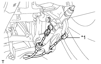
Text in Illustration *1 Control Shift Cable Install the control shift cable to the shift lever assembly.
-
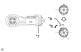
Text in Illustration *1 Stopper *a 34° *b Turn Release the lock of the cable length adjustment structure of the select cable.
-
Turn the stopper.
-
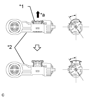
Text in Illustration *1 Lock Piece *2 Case *a Pull Out Pull the lock piece outward from the case to release the lock.
-
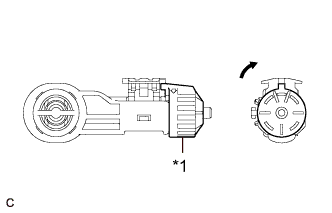
Text in Illustration *1 Stopper 
Return Return the stopper.
-
-
While pressing the shift and select lever shaft (*1) and pin (*2), push in the pin (*3) and check that the shift and select lever shaft is secured at the 1st-2nd gear selected position (the shaft comes to a stop at the position 8 mm (0.315 in.) below the N position).
-
Connect the control select cable to the shift lever assembly.
-
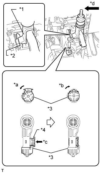
Text in Illustration *1 Slider *2 Inhibitor Wall *3 Stopper *4 Lock Piece *a Turn *b Return *c Push *d Press with a force of 20 N*m (204 kgf*cm, 15 ft.*lbf) Push the slider against the inhibitor wall.
Note
-
Press the slider against the inhibitor wall with a force of 20 N*m (204 kgf*cm, 15 ft.*lbf) as shown in the illustration.
-
Keep pressing the slider against the inhibitor wall until the cable adjustment is completed.
-
Do not pull up the slider.
-
When adjusting the cable, make sure that the shift lever is not in the 1 or 2.
-
-
Lock the cable length adjustment structure of the select cable.
-
Turn the stopper.
-
Push the lock piece into the case.
Note
Do not move the cable in the axial direction.
-
Return the stopper to prevent the lock from being released.
Note
-
Push the lock piece as far as it will go.
-
Confirm whether the cable length adjustment structure is locked securely.
-
-
-
Release the pin that fixes the shift and select lever shaft.
Text in Illustration Pull
-
Pull the pin toward the left front side of the vehicle.
-
-
-
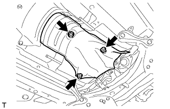
INSTALL FRONT NO. 1 FLOOR HEAT INSULATOR
-
Install the front No. 1 floor heat insulator with the 3 nuts.
- Torque:
- 5.5 N*m { 56 kgf*cm, 49 in.*lbf }
-
-
INSTALL LOWER NO. 1 INSTRUMENT PANEL FINISH PANEL
-
CONNECT NO. 1 AIR TUBE ASSEMBLY
-
Connect the No. 1 air tube assembly to the manual transaxle assembly with the 2 bolts.
- Torque:
- 20 N*m { 204 kgf*cm, 15 ft.*lbf }
-
Connect the outlet heater water hose to the No. 2 radiator pipe, and slide the clamp to secure the hose.
-
Connect the water hose sub-assembly to the No. 1 radiator pipe, and slide the clamp to secure the hose.
-
Attach the clamp and connect the water hose sub-assembly to the compressor outlet elbow.
-
Connect the water by-pass hose assembly to the No. 2 radiator pipe, and slide the clamp to secure the hose.
-
Connect the radiator hose sub-assembly to the No. 1 radiator pipe, and slide the clamp to secure the hose.
-
-
CONNECT COMPRESSOR OUTLET ELBOW
-
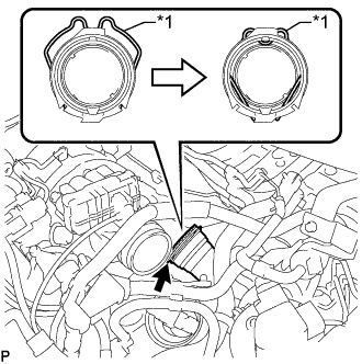
Text in Illustration *1 Retainer Connect the compressor outlet elbow to the turbocharger sub-assembly and lock the retainer as shown in the illustration.
-
-
INSTALL NO. 4 WATER BY-PASS HOSE
-
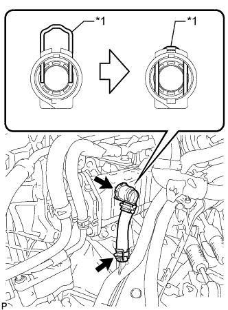
Text in Illustration *1 Retainer Install the No. 4 water by-pass hose to the No. 2 radiator pipe, and slide the clamp to secure the hose.
-
Connect the No. 4 water by-pass hose to the EGR cooler assembly and lock the retainer as shown in the illustration.
-
-
CONNECT ENGINE WIRE
-
Connect the engine wire to the No. 1 air tube assembly with the 2 bolts.
- Torque:
- 8.4 N*m { 86 kgf*cm, 74 in.*lbf }
-
Attach the 2 clamps to the No. 1 air tube assembly.
-
-
INSTALL AIR CLEANER CASE SUB-ASSEMBLY
-
INSTALL AIR CLEANER FILTER ELEMENT SUB-ASSEMBLY
-
INSTALL AIR CLEANER CAP SUB-ASSEMBLY WITH AIR CLEANER HOSE ASSEMBLY
-
INSTALL BATTERY CARRIER
-
Install the battery carrier with the 4 bolts.
- Torque:
- 19 N*m { 189 kgf*cm, 14 ft.*lbf }
-
Attach the 2 clamps to connect the engine wire.
-
-
INSTALL BATTERY TRAY
-
INSTALL BATTERY
-
INSTALL BATTERY INSULATOR
-
INSTALL BATTERY CLAMP SUB-ASSEMBLY
-
Attach the hook of the battery clamp sub-assembly to the battery carrier.
-
Partially tighten the nut and temporarily install the bolt.
-
Adjust the battery clamp sub-assembly position.
-
Tighten the nut and bolt.
- Torque:
- for bolt
- 17 N*m { 168 kgf*cm, 12 ft.*lbf }
- for nut
- 3.5 N*m { 36 kgf*cm, 31 in.*lbf }
-
-
INSTALL FRONT EXHAUST PIPE ASSEMBLY
-
ADD ENGINE COOLANT
CAUTION:
Do not remove the reservoir cap and air release valve while the engine and radiator assembly are still hot. Pressurized, hot engine coolant and steam may be released and cause serious burns.
-
Tighten the radiator drain cock plug by hand.
-
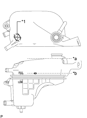
Text in Illustration *1 Air Release Valve *a Radiator Reservoir Assembly Filler Neck *b Pour Limit Line Remove the air release valve.
-
Add engine coolant to the pour limit line of the radiator reservoir assembly.
Standard Capacity Item Specified Condition w/o Combustion Type Power Heater 7.0 liters (7.4 US qts, 6.2 Imp. qts) w/ Combustion Type Power Heater 7.3 liters (7.7 US qts, 6.4 Imp. qts) Note
Never use water as a substitute for engine coolant.
Tech Tips
Toyota recommends the use of approved "Toyota Premium Long Life Coolant for 1WW/2WW engines" or equivalent.
-
Press the No. 2 radiator hose and radiator hose sub-assembly several times by hand, and then check the level of the engine coolant.
If the coolant level is low, add engine coolant.
-
Install the air release valve.
-
Add engine coolant to the filler neck of the radiator reservoir assembly.
-
Install the reservoir cap.
-
Start the engine, and warm it up until the cooling fan operates.
Note
-
Before starting the engine, turn the A/C switch off.
-
Adjust the air conditioning temperature setting to MAX (HOT).
-
Adjust the air conditioning blower setting to Lo.
-
-
Maintain the engine speed at 2000 to 2500 rpm and warm up the engine until the cooling fan operates.
Note
-
Make sure that the radiator reservoir assembly still has some engine coolant in it.
-
Pay attention to the needle of the water temperature meter. Make sure that the needle does not show an abnormally high temperature.
-
If there is not enough engine coolant, the engine may burn out or overheat.
-
Immediately after starting the engine, if the radiator reservoir assembly does not have any coolant, perform the following: 1) stop the engine, 2) wait until the engine coolant has cooled down, and 3) add engine coolant until the coolant is filled to the pour limit line.
-
Until the coolant level has stabilized, run the engine at 2000 rpm.
-
-
Press the No. 2 radiator hose and radiator hose sub-assembly several times by hand to bleed air.
CAUTION:
-
Wear protective gloves.
-
Be careful as the radiator hoses are hot.
-
Keep your hands away from the cooling fan.
-
-
Stop the engine and wait until the coolant cools down to ambient temperature.
-
Check that the coolant level is between the FULL and LOW line.
If the coolant level is below the LOW line, repeat all of the procedures above.
If the coolant level is above the FULL line, drain coolant so that the coolant level is between the FULL and LOW line.
-
-
CONNECT CABLE TO POSITIVE BATTERY TERMINAL
-
CONNECT CABLE TO NEGATIVE BATTERY TERMINAL
Note
When disconnecting the cable, some systems need to be initialized after the cable is reconnected Click here.
-
INSPECT COOLANT LEAK
-
Remove the reservoir cap.
CAUTION:
To avoid the danger of being burned, do not remove the reservoir cap while the engine and radiator assembly are still hot. Thermal expansion will cause hot engine coolant and steam to blow out from the radiator assembly.
-
Fill the radiator assembly with coolant, and then attach a radiator cap tester.
-
Warm up the engine.
-
Pump the radiator cap tester to 143 kPa (1.5 kgf/cm2, 20.7 psi), and then check that the pressure does not drop.
If the pressure drops, check the hoses, radiator assembly and engine water pump assembly for leakage.
If there are no signs of external coolant leaks, check the heater core, cylinder block and head.
-
Reinstall the reservoir cap.
-
-
INSPECT EXHAUST GAS LEAK
-
INSTALL RADIATOR SUPPORT OPENING COVER
-
Attach the 4 hooks and install the radiator support opening cover.
-
Install the 3 clips.
-
-
INSTALL NO. 1 ENGINE COVER
-
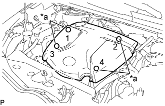
Text in Illustration *a Installation Points Attach the 4 clips to install the No. 1 engine cover.
Tech Tips
When attaching the clips, press the protrusions on the top of the No. 1 engine cover at the clip installation points.
-
-
INSTALL NO. 1 ENGINE UNDER COVER
-
Install the No. 1 engine under cover with the 11 clips and 6 bolts.
-