TRANSMISSION CONTROL CABLE (for 1WW) REMOVAL

-
PRECAUTION
Note
After turning the ignition switch off, waiting time may be required before disconnecting the cable from the battery terminal. Therefore, make sure to read the disconnecting the cable from the battery terminal notice before proceeding with work Click here
-
DISCONNECT CABLE FROM NEGATIVE BATTERY TERMINAL
Note
When disconnecting the cable, some systems need to be initialized after the cable is reconnected Click here.
-
DISCONNECT CABLE FROM POSITIVE BATTERY TERMINAL
-
REMOVE NO. 1 ENGINE UNDER COVER
-
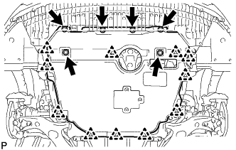
Remove the 6 bolts and 11 clips.
-
Remove the No. 1 engine under cover.
-
-
REMOVE FRONT EXHAUST PIPE ASSEMBLY
-
REMOVE RADIATOR SUPPORT OPENING COVER
-
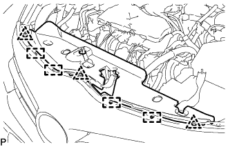
Remove the 3 clips.
-
Detach the 4 hooks and remove the radiator support opening cover.
-
-
REMOVE NO. 1 ENGINE COVER
-
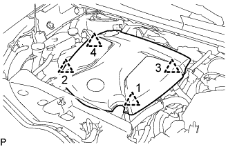
Lift the No. 1 engine cover to detach the 4 clips in the order shown in the illustration and remove the No. 1 engine cover.
Note
Attempting to disengage both front and rear clips at the same time may cause the No. 1 engine cover to break.
-
-
DRAIN ENGINE COOLANT
CAUTION:
Do not remove the reservoir cap and air release valve while the engine and radiator assembly are still hot. Pressurized, hot engine coolant and steam may be released and cause serious burns.
-
Loosen the radiator drain cock plug and drain the engine coolant.
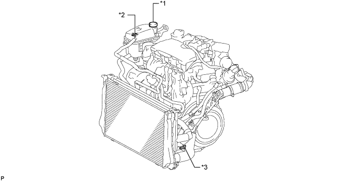
Text in Illustration *1 Reservoir Cap *2 Air Release Valve *3 Radiator Drain Cock Plug - - Tech Tips
Collect the coolant in a container and dispose of it according to the regulations in your area.
-
Remove the reservoir cap.
-
-
REMOVE BATTERY CLAMP SUB-ASSEMBLY
-
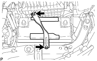
Remove the bolt and loosen the nut.
-
Detach the hook of the battery clamp sub-assembly from the battery carrier, and then remove the battery clamp sub-assembly.
-
-
REMOVE BATTERY INSULATOR
-
REMOVE BATTERY
-
REMOVE BATTERY TRAY
-
REMOVE BATTERY CARRIER
-
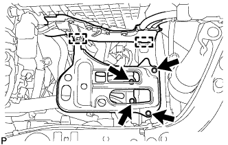
Detach the 2 clamps and disconnect the engine wire.
-
Remove the 4 bolts and battery carrier.
-
-
REMOVE AIR CLEANER CAP SUB-ASSEMBLY WITH AIR CLEANER HOSE ASSEMBLY
-
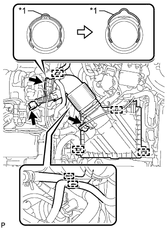
Text in Illustration *1 Retainer Detach the clamp and disconnect the mass air flow meter sub-assembly connector.
-
Detach the clamp and disconnect the vacuum hose from the air cleaner hose assembly.
-
Detach the clamp and disconnect the No. 1 fuel hose from the air cleaner hose assembly.
-
Detach the clamp and disconnect the No. 2 fuel hose from the air cleaner hose assembly.
-
Disconnect the ventilation hose from the cylinder head cover sub-assembly.
-
Release the retainer and disconnect the air cleaner hose assembly from the turbocharger sub-assembly as shown in the illustration.
-
Detach the 2 clamps and remove the air cleaner cap sub-assembly with air cleaner hose assembly.
-
-
REMOVE AIR CLEANER FILTER ELEMENT SUB-ASSEMBLY
-
REMOVE AIR CLEANER CASE SUB-ASSEMBLY
-

Remove the 3 bolts and air cleaner case sub-assembly.
-
-
DISCONNECT ENGINE WIRE
-
Detach the 2 clamps from the No. 1 air tube assembly.
-
Remove the 2 bolts and disconnect the engine wire from the No. 1 air tube assembly.
-
-
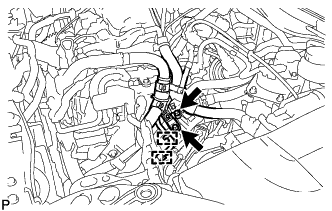
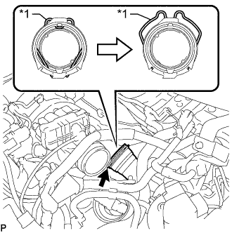
REMOVE NO. 4 WATER BY-PASS HOSE
-
Text in Illustration *1 Retainer Release the retainer and disconnect the No. 4 water by-pass hose from the EGR cooler assembly as shown in the illustration.
-
Slide the clamp and remove the No. 4 water by-pass hose from the No. 2 radiator pipe.
-
-
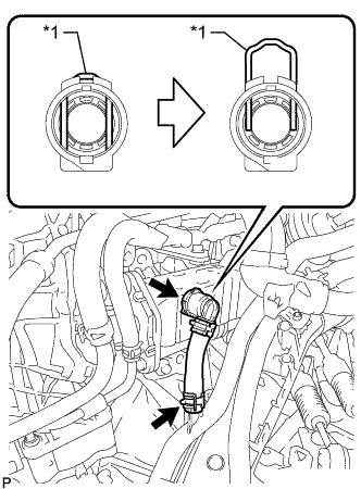
DISCONNECT COMPRESSOR OUTLET ELBOW
-
Text in Illustration *1 Retainer Release the retainer and disconnect the compressor outlet elbow from the turbocharger sub-assembly as shown in the illustration.
-
-
DISCONNECT NO. 1 AIR TUBE ASSEMBLY
-
Slide the clamp and disconnect the water by-pass hose assembly from the No. 2 radiator pipe.
-
Slide the clamp and disconnect the radiator hose sub-assembly from the No. 1 radiator pipe.
-
Detach the clamp and disconnect the water hose sub-assembly from the compressor outlet elbow.
-
Slide the clamp and disconnect the water hose sub-assembly from the No. 1 radiator pipe.
-
Slide the clamp and disconnect the outlet heater water hose from the No. 2 radiator pipe.
-
Remove the 2 bolts and disconnect the No. 1 air tube assembly from the manual transaxle assembly.
-
-
REMOVE LOWER NO. 1 INSTRUMENT PANEL FINISH PANEL
-
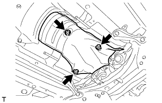
REMOVE FRONT NO. 1 FLOOR HEAT INSULATOR
-
Remove the 3 nuts and front No. 1 floor heat insulator.
-
-
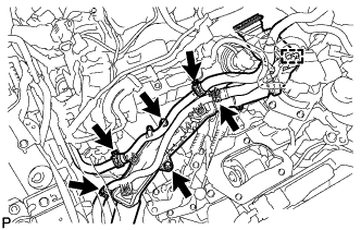
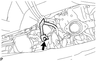
REMOVE TRANSMISSION CONTROL CABLE ASSEMBLY
-
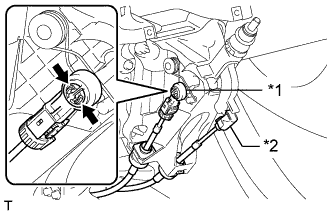
Text in Illustration *1 Control Select Cable *2 Control Shift Cable Disconnect the control shift cable from the shift lever assembly.
-
Pinch the areas indicated by the arrows and disconnect the control select cable.
-
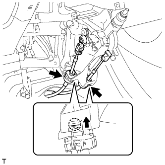
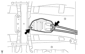
Detach the 2 claws and disconnect the transmission control cable assembly.
-
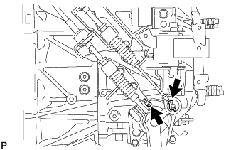
Remove the 2 clips and disconnect the 2 cables from the manual transaxle assembly.
-
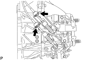
Remove the 2 clips and disconnect the 2 cables from the control cable bracket.
-
Remove the bolt and detach the bracket of the transmission control cable assembly.
-
Remove the 2 nuts and detach the grommet of the transmission control cable assembly.
-