CLUTCH PEDAL SWITCH INSTALLATION

-
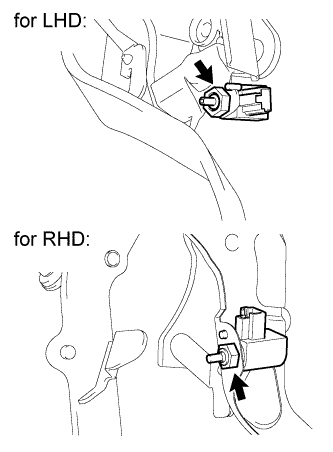
INSTALL CLUTCH START SWITCH ASSEMBLY
-
Install the clutch start switch assembly with the nut.
- Torque:
- 16 N*m { 160 kgf*cm, 12 ft.*lbf }
-
Connect the clutch start switch assembly connector.
-
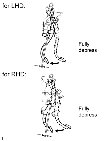
With the clutch pedal fully depressed, check the clearance between the pedal and switch body.
Standard Clearance Item Specified Condition for LHD 1.7 to 4.7 mm (0.0669 to 0.185 in.) for RHD 2.7 to 5.7 mm (0.106 to 0.224 in.)
-
-
INSPECT CLUTCH START SWITCH ASSEMBLY
-
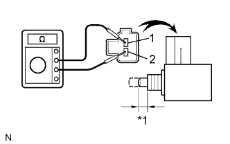
Text in Illustration *1 7.65 to 8.35 mm (0.301 to 0.329 in.) Measure the resistance according to the value(s) in the table below.
Standard Resistance Tester Connection Switch Condition Specified Condition 1 - 2 On (pushed) Below 1 Ω Off (free) 10 kΩ or higher If the result is not as specified, replace the clutch start switch assembly.
-