CLUTCH PEDAL (for LHD) INSTALLATION

-
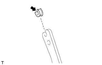
INSTALL CLUTCH PEDAL TURNOVER BUSH
-
Install the clutch pedal turnover bush to the clutch pedal sub-assembly.
-
Apply MP grease to the inside of the clutch pedal turnover bush.
Text in Illustration 
MP grease
-
-
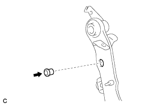
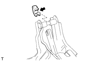
INSTALL CLUTCH MASTER CYLINDER PUSH ROD CLEVIS BUSHING
-
Apply MP grease to the inside of a new clutch master cylinder push rod clevis bushing.
Text in Illustration MP grease -
Install the clutch master cylinder push rod clevis bushing to the clutch pedal sub-assembly.
Tech Tips
Install the clutch master cylinder push rod clevis bushing from the left side of the vehicle.
-
-
INSTALL NO. 1 CLUTCH PEDAL CUSHION
-
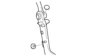
Install the 2 No. 1 clutch pedal cushions to the clutch pedal sub-assembly.
-
-
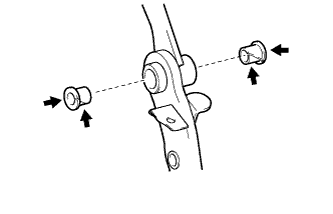
INSTALL CLUTCH PEDAL BUSHING
-
Apply MP grease to both sides of 2 new clutch pedal bushings.
Text in Illustration MP grease -
Install the 2 clutch pedal bushings to the clutch pedal sub-assembly.
-
-
INSTALL CLUTCH PEDAL PAD
-
Install the clutch pedal pad to the clutch pedal sub-assembly.
-
-
INSTALL CLUTCH PEDAL SUB-ASSEMBLY
-
Install the clutch pedal sub-assembly to the clutch pedal support sub-assembly with the bolt and nut.
- Torque:
- 37 N*m { 375 kgf*cm, 27 ft.*lbf }
Tech Tips
Install the bolt from the right side of the vehicle.
-
-
INSTALL PEDAL SPRING HOOK (for 2AD-FHV)
-
Apply MP grease to the contact surface of the pedal spring hook.
Text in Illustration MP grease -
Install the pedal spring hook.
-
-
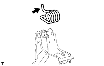
INSTALL PEDAL WITH HOOK SPRING (for 2AD-FHV)
-
Apply MP grease to the contact surface of the hook spring.
Text in Illustration 
MP grease -
Install the hook spring.
-
-
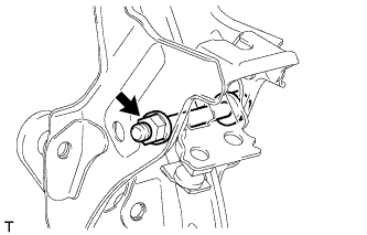
INSTALL CLUTCH PEDAL STOPPER BOLT
-
Install the clutch pedal stopper bolt together with the nut so that its end touches the No. 1 clutch pedal cushion.
Tech Tips
Tighten the lock nut to the specified torque when adjusting the clutch pedal.
-
-
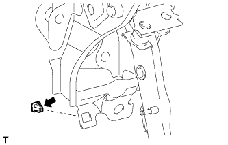
INSTALL CLUTCH PEDAL SPRING HOLDER
-
Apply MP grease to the contact surface of the clutch pedal spring holder.
Text in Illustration MP grease -
Install the clutch pedal spring holder to the clutch pedal support sub-assembly.
-
-
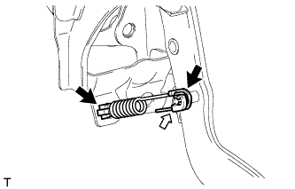
INSTALL TURN OVER SPRING SEAT COMPRESSION SPRING
-
Apply MP grease to the contact surfaces of the clutch pedal spring holder and turn over seat compression spring.
Text in Illustration MP grease -
Install the turn over seat compression spring to the clutch pedal and clutch pedal spring holder.
-
-
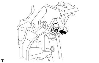
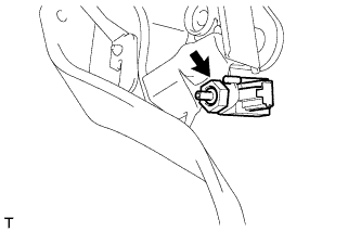
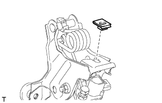
INSTALL CLUTCH START SWITCH ASSEMBLY
-
Install the clutch start switch assembly with the nut.
- Torque:
- 16 N*m { 160 kgf*cm, 12 ft.*lbf }
-
-
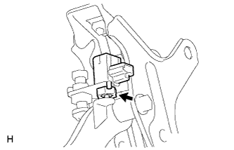
INSTALL CLUTCH SWITCH ASSEMBLY
-
Install the clutch switch assembly with the nut.
- Torque:
- 16 N*m { 160 kgf*cm, 12 ft.*lbf }
-
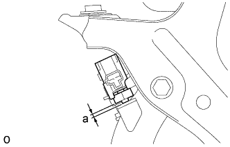
With the clutch pedal fully depressed, check the clearance.
Standard Measurement Area Item Specified Condition a for 1AD-FTV, 2AD-FHV, 1WW 0.5 to 3.5 mm (0.0197 to 0.138 in.) for 1ZR-FAE, 2ZR-FAE 0.9 to 3.9 mm (0.0354 to 0.154 in.)
-
-
INSTALL CLUTCH PEDAL SUPPORT SUB-ASSEMBLY
-
Install the nut to the clutch pedal support sub-assembly.
-
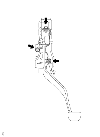
Install the clutch pedal support sub-assembly with the 2 nuts and bolt.
- Torque:
- for bolt
- 24 N*m { 241 kgf*cm, 17 ft.*lbf }
- for nut
- 18 N*m { 178 kgf*cm, 13 ft.*lbf }
-
Connect the clutch start switch assembly connector and clutch switch assembly connector.
-
-
INSTALL CLUTCH MASTER CYLINDER PUSH ROD CLEVIS WITH HOLE PIN
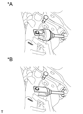
Text in Illustration *A for Gasoline *B for Diesel MP grease
-
Apply MP grease to the contact surface of the clutch master cylinder push rod clevis with hole pin.
-
Connect the clevis to the clutch pedal sub-assembly with the clutch master cylinder push rod clevis with hole pin.
Tech Tips
Install the clutch master cylinder push rod clevis with hole pin from the right side of the vehicle.
-
Install a new clip to the clutch master cylinder push rod clevis with hole pin.
-
-
INSPECT AND ADJUST CLUTCH PEDAL SUB-ASSEMBLY
-
Inspect and adjust the clutch pedal sub-assembly Click here.
-
-
INSTALL LOWER NO. 1 INSTRUMENT PANEL AIRBAG ASSEMBLY
-
Install the lower No. 1 instrument panel airbag assembly Click here.
-
-
INSTALL INSTRUMENT PANEL SAFETY PAD SUB-ASSEMBLY
-
Install the instrument panel safety pad sub-assembly Click here.
-