-
Click here
INSTALL CLUTCH PEDAL TURNOVER BUSH (except 1ZR-FAE)
-
Install the clutch pedal turnover bush to the clutch pedal sub-assembly.
-
Apply MP grease to the inside of the clutch pedal turnover bush.
Table 1. Text in Illustration *1 MP grease
-
-
Click here
INSTALL CLUTCH MASTER CYLINDER PUSH ROD CLEVIS BUSHING
-
Apply MP grease to the inside of a new clutch master cylinder push rod clevis bushing.
Table 2. Text in Illustration *1 MP grease -
Install the clutch master cylinder push rod clevis bushing to the clutch pedal sub-assembly.
Tip:Install the clutch master cylinder push rod clevis bushing from the left side of the vehicle.
-
- Click here
INSTALL NO. 1 CLUTCH PEDAL CUSHION
-
Install the 2 No. 1 clutch pedal cushions to the clutch pedal sub-assembly.
-
-
Click here
INSTALL CLUTCH PEDAL BUSHING
-
Apply MP grease to both sides of 2 new clutch pedal bushings.
Table 3. Text in Illustration *1 MP grease -
Install the 2 clutch pedal bushings to the clutch pedal sub-assembly.
-
- Click here
INSTALL CLUTCH PEDAL PAD
-
Install the clutch pedal pad to the clutch pedal sub-assembly.
-
- Click here
INSTALL CLUTCH PEDAL SUB-ASSEMBLY
-
Install the clutch pedal sub-assembly to the clutch pedal support sub-assembly with the bolt and nut.
37 N*m 375 kgf*cm 27 ft.*lbf Tip:Install the bolt from the right side of the vehicle.
-
-
Click here
INSTALL PEDAL SPRING HOOK (for 1AD-FTV, 2AD-FHV)
-
Apply MP grease to the contact surface of the pedal spring hook.
Table 4. Text in Illustration *1 MP grease -
Install the pedal spring hook.
-
-
Click here
INSTALL PEDAL WITH HOOK SPRING (for 1AD-FTV, 2AD-FHV)
-
Apply MP grease to the contact surface of the hook spring.
Table 5. Text in Illustration *1 MP grease -
Install the hook spring.
-
-
Click here
INSTALL CLUTCH PEDAL SPRING (for 1ZR-FAE)
-
Apply MP grease to the sliding portions of the clutch pedal spring.
Table 6. Text in Illustration *1 MP grease -
Install the clutch pedal spring.
-
- Click here
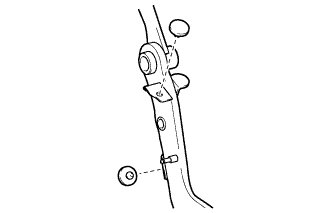
INSTALL CLUTCH PEDAL STOPPER BOLT
-
Install the clutch pedal stopper bolt together with the nut so that its end touches the No. 1 clutch pedal cushion.
Tip:Tighten the lock nut to the specified torque when adjusting the clutch pedal.
-
-
Click here
INSTALL CLUTCH PEDAL SPRING HOLDER (except 1ZR-FAE)
-
Apply MP grease to the contact surface of the clutch pedal spring holder.
Table 7. Text in Illustration *1 MP grease -
Install the clutch pedal spring holder to the clutch pedal support sub-assembly.
-
-
Click here
INSTALL TURN OVER SPRING SEAT COMPRESSION SPRING (except 1ZR-FAE)
-
Apply MP grease to the contact surfaces of the clutch pedal spring holder and turn over seat compression spring.
Table 8. Text in Illustration *1 MP grease -
Install the turn over seat compression spring to the clutch pedal and clutch pedal spring holder.
-
-
Click here
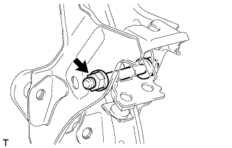
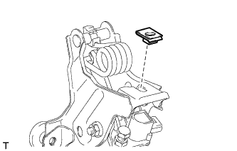
INSTALL CLUTCH START SWITCH ASSEMBLY
-
Install the clutch start switch assembly with the nut.
16 N*m 160 kgf*cm 12 ft.*lbf
-
-
Click here
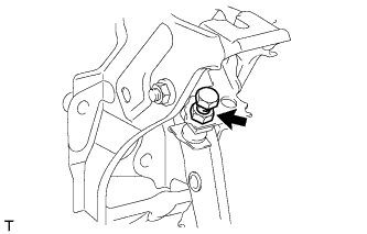
INSTALL CLUTCH SWITCH ASSEMBLY
-
Install the clutch switch assembly with the nut.
16 N*m 160 kgf*cm 12 ft.*lbf -
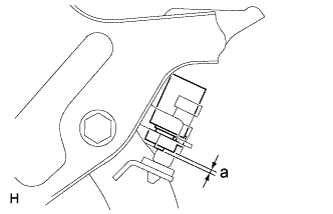
With the clutch pedal fully depressed, check the clearance.
Standard Measurement Area Item Specified Condition a for 1AD-FTV, 2AD-FHV 0.2 to 3.2 mm (0.0079 to 0.126 in.) for 1ZR-FAE 2 to 5 mm (0.0787 to 0.197 in.) for 2ZR-FAE 1.1 to 4.1 mm (0.433 to 0.161 in.)
-
- Click here
INSTALL CLUTCH PEDAL SUPPORT SUB-ASSEMBLY
-
Install the nut to the clutch pedal support sub-assembly.
-
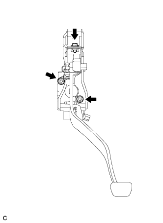
Install the clutch pedal support sub-assembly with the 2 nuts and bolt.
for bolt 24 N*m 241 kgf*cm 17 ft.*lbf for nut 18 N*m 178 kgf*cm 13 ft.*lbf -
Connect the clutch start switch assembly connector and clutch switch assembly connector.
-
-
Click here
INSTALL CLUTCH MASTER CYLINDER PUSH ROD CLEVIS WITH HOLE PIN
-
Apply MP grease to the contact surface of the clutch master cylinder push rod clevis with hole pin.
Table 9. Text in Illustration *1 MP grease -
Connect the clevis to the clutch pedal sub-assembly with the clutch master cylinder push rod clevis with hole pin.
Tip:Install the clutch master cylinder push rod clevis with hole pin from the right side of the vehicle.
-
Install a new clip to the clutch master cylinder push rod clevis with hole pin.
-
- Click here
INSPECT AND ADJUST CLUTCH PEDAL SUB-ASSEMBLY
-
Inspect and adjust the clutch pedal sub-assembly (Click here).
-
- Click here
INSTALL LOWER NO. 1 INSTRUMENT PANEL AIRBAG ASSEMBLY
-
Install the lower No. 1 instrument panel airbag assembly (Click here).
-
- Click here
INSTALL INSTRUMENT PANEL SAFETY PAD SUB-ASSEMBLY
-
Install the instrument panel safety pad sub-assembly (Click here).
-