DIFFERENTIAL CASE DISASSEMBLY

-
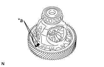
REMOVE FRONT DIFFERENTIAL RING GEAR
-
Put matchmarks on the front differential ring gear and differential case.
Text in Illustration *a Matchmark -
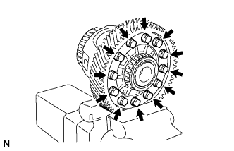
Remove the 12 bolts.
-
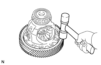
Using a plastic-faced hammer, tap on the front differential ring gear to remove it from the differential case.
-
-
REMOVE FRONT DIFFERENTIAL CASE FRONT TAPERED ROLLER BEARING
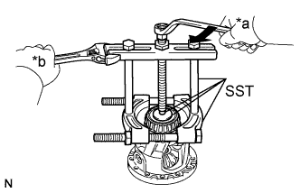
Text in Illustration *a Turn *b Hold
-
Using SST, remove the front differential case front tapered roller bearing from the differential case.
- SST
- 09950-00020
- 09950-00030
- 09950-60010 ( 09951-00480 )
-
-
REMOVE FRONT DIFFERENTIAL CASE REAR TAPERED ROLLER BEARING
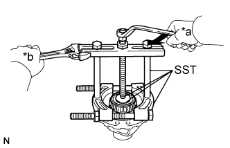
Text in Illustration *a Turn *b Hold
-
Using SST, remove the front differential case rear tapered roller bearing from the differential case.
- SST
- 09950-00020
- 09950-00030
- 09950-60010 ( 09951-00480 )
-
-
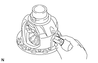
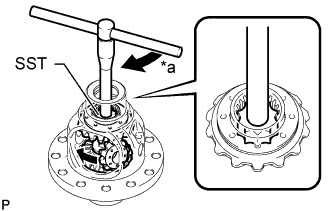
INSPECT DIFFERENTIAL CASE
-
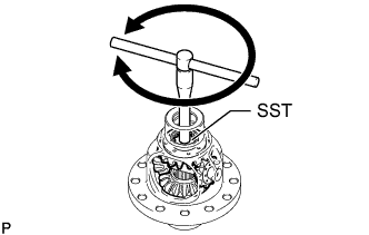
Using SST, rotate the differential side gear as shown in the illustration.
- SST
- 09528-52010 ( 09528-05030 )
Standard The front differential side gear does not lock when rotated in either direction.
-
If the differential side gear locks, perform all remaining inspection procedures.
-
Replace any parts that do not meet the specifications.
-
If the differential side gear locks after performing the inspection procedures, replace the differential case.
-
-
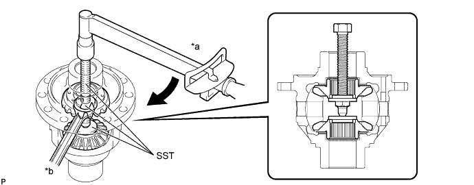
INSPECT DIFFERENTIAL SIDE GEAR THRUST AMOUNT
-
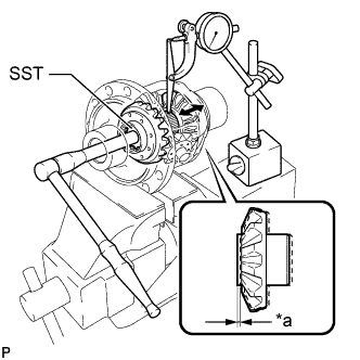
Text in Illustration *a Thrust Amount Using SST and a dial indicator, measure the thrust amount of the differential side gear.
- SST
- 09528-52010 ( 09528-05030 )
Standard Thrust Amount 0.08 mm (0.00314 in.) or less Tech Tips
-
Measure the differential side gear thrust amount while slowly rotating the differential side gear.
-
Make sure to measure the differential side gear thrust amount for both of the differential side gears.
If the result is not as specified, replace the 2 conical spring washers, 2 differential side gears and 2 front differential pinions.
-
-
REMOVE FRONT DIFFERENTIAL PINION SHAFT STRAIGHT PIN
-
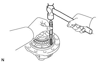
Using a 5 mm pin punch and hammer, remove the front differential pinion shaft straight pin from the differential case.
-
-
REMOVE NO. 1 FRONT DIFFERENTIAL PINION SHAFT
-
Remove the No. 1 front differential pinion shaft from the differential case.
-
-
INSPECT DIFFERENTIAL SIDE GEAR BACKLASH
-
Set SST as shown in the illustration and tighten it.
- SST
- 09528-52010 ( 09528-05010, 09953-05010 )
- Torque:
- 10 N*m { 102 kgf*cm, 7 ft.*lbf }
Text in Illustration *a Turn *b Hold -
Hold the differential case in a vise between aluminum plates.
Note
Do not overtighten the vise.
-
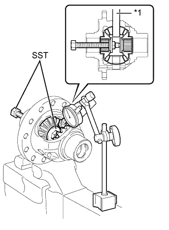
Text in Illustration *1 No. 1 Front Differential Pinion Shaft Install the No. 1 front differential pinion shaft to the front differential pinion as shown in the illustration.
-
Using SST and a dial indicator, measure the front differential pinion backlash.
- SST
- 09528-52010 ( 09528-05010, 09953-05010 )
Standard Backlash 0.05 to 0.15 mm (0.00197 to 0.00590 in.) If the backlash is not as specified, replace the No. 1 front differential side gear thrust washers with washers of a different thickness. Use the table below to select a No. 1 front differential side gear thrust washer which will ensure that the backlash is within the specification.
No. 1 Front Differential Side Gear Thrust Washer Thickness Thickness Thickness 1.50 mm (0.0591 in.) 1.75 mm (0.0689 in.) 1.55 mm (0.0610 in.) 1.80 mm (0.0709 in.) 1.60 mm (0.0630 in.) 1.85 mm (0.0728 in.) 1.65 mm (0.0650 in.) 1.90 mm (0.0748 in.) 1.70 mm (0.0669 in.) - Tech Tips
Select front No. 1 differential side gear thrust washers of the same thickness for both the right and left side.
-
-
REMOVE DIFFERENTIAL SIDE GEAR
-
Set SST as shown in the illustration and tighten it.
- SST
- 09528-52010 ( 09953-05010, 09528-05010 )
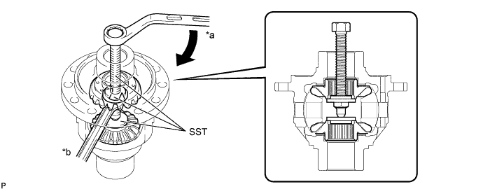
Text in Illustration *a Turn *b Hold Note
Do not overtighten SST, as doing so will damage the differential side gear, conical spring washer, No. 1 front differential side gear thrust washer and differential case.
Tech Tips
-
Tighten SST until there is a clearance between the front differential pinions and differential side gears.
-
When removing the front differential pinions, do not overtighten SST, as it is necessary to rotate the differential side gears.
-
Text in Illustration *a Turn Install SST as shown in the illustration, rotate the differential side gear, and then remove the 2 front differential pinions and 2 front differential pinion thrust washers from the differential case.
- SST
- 09528-52010 ( 09528-05030 )
Note
Do not drop the front differential pinions and front differential pinion thrust washers.
-
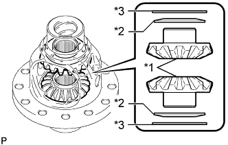
Text in Illustration *1 Differential Side Gear *2 Conical Spring Washer *3 No. 1 Front Differential Side Gear Thrust Washer Remove SST from the differential case, and then remove the 2 differential side gears, 2 No. 1 front differential side gear thrust washers and 2 conical spring washers from the differential case.
-