AUTOMATIC TRANSAXLE UNIT REASSEMBLY

-
BEARING POSITION
-
Check the position and installation direction of the bearing.
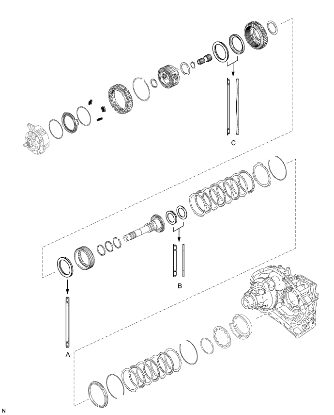
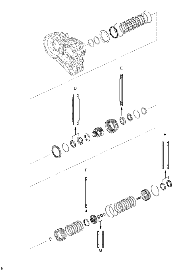
Bearing Position Mark Front Race Diameter
Inside/Outside
Thrust Bearing Diameter
Inside/Outside
Rear Race Diameter
Inside/Outside
A - 57.7 mm (2.27 in.)/75.2 mm (2.96 in.) - B - 29.1 mm (1.15 in.)/48.6 mm (1.91 in.) 30.7 mm (1.21 in.)/48.3 mm (1.90 in.) C 65.9 mm (2.59 in.)/80.3 mm (3.16 in.) 62.6 mm (2.47 in.)/82.4 mm (3.24 in.) - D 59.4 mm (2.34 in.)/77 mm (3.03 in.) 53.1 mm (2.09 in.)/79 mm (3.11 in.) - E - 56.1 mm (2.21 in.)/80.9 mm (3.19 in.) - F - 61.2 mm (2.41 in.)/79 mm (3.11 in.) - G - 28 mm (1.10 in.)/47.1 mm (1.85 in.) 26.1 mm (1.03 in.)/44 mm (1.73 in.) H 52.2 mm (2.06 in.)/70.4 mm (2.77 in.) 48.9 mm (1.93 in.)/72.0 mm (2.84 in.) -
-
-
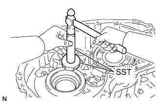
INSTALL COUNTER DRIVEN GEAR BEARING OUTER RACE (REAR)
-
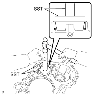
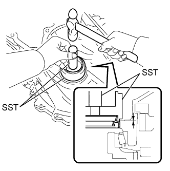
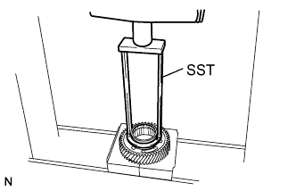
Using SST and a hammer, tap in a new counter driven gear bearing outer race to the transaxle case.
- SST
- 09950-60010 ( 09951-00650 )
- 09950-70010 ( 09951-07100 )
Note
Be sure to install the counter driven gear bearing outer race so that there is no clearance between the bearing outer race and the transaxle case. If there is any clearance, the turning torque of the counter drive gear cannot be measured correctly.
-
-
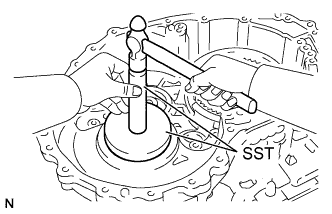
INSTALL FRONT DIFFERENTIAL CASE REAR TAPERED ROLLER BEARING OUTER RACE
-
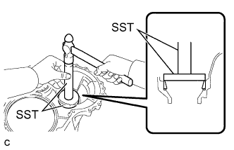
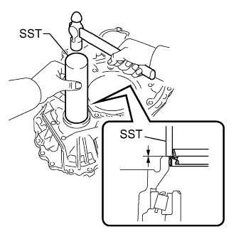
Using SST and a hammer, tap in a new front differential case rear tapered roller bearing outer race to the transaxle case.
- SST
- 09950-60020 ( 09951-00790 )
- 09950-70010 ( 09951-07150 )
Note
Be sure to install the front differential case rear tapered roller bearing outer race so that there is no clearance between the bearing outer race and the transaxle case. If there is any clearance, the turning torque of the counter drive gear cannot be measured correctly.
-
-
INSTALL COUNTER DRIVEN GEAR BEARING OUTER RACE (FRONT)
-
Install the shim to the transaxle housing.
-
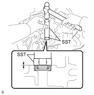
Using SST, install a new counter driven gear bearing outer race to the transaxle housing.
- SST
- 09950-60020 ( 09951-00810 )
- 09950-70010 ( 09951-07100 )
Note
Be sure to install the counter driven gear bearing outer race so that there is no clearance between the bearing outer race and the transaxle housing. If there is any clearance, the turning torque of the counter drive gear cannot be measured correctly.
-
-
INSTALL FRONT DIFFERENTIAL CASE FRONT TAPERED ROLLER BEARING OUTER RACE
-
Install the shim to the transaxle housing.
-
Using SST and a hammer, tap in a new differential case bearing outer race to the transaxle housing.
- SST
- 09950-60010 ( 09951-00480 )
- 09950-70010 ( 09951-07150 )
Note
Be sure to install the differential case bearing outer race so that there is no clearance between the bearing outer race and the transaxle housing. If there is any clearance, the turning torque of the counter drive gear cannot be measured correctly.
-
-
ADJUST FRONT DIFFERENTIAL CASE BEARING PRELOAD
-
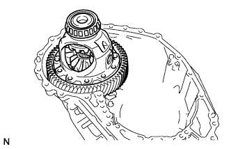
Install the front differential case to the transaxle case.
-
Clean the contact surfaces of the transaxle case and transaxle housing.
-
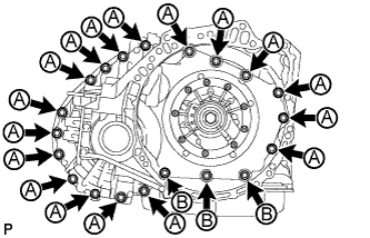
Install the transaxle housing to the transaxle case with the 20 bolts.
- Torque:
- for bolt A
- 31 N*m { 312 kgf*cm, 23 ft.*lbf }
- for bolt B
- 23 N*m { 231 kgf*cm, 17 ft.*lbf }
-
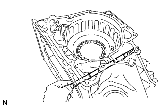
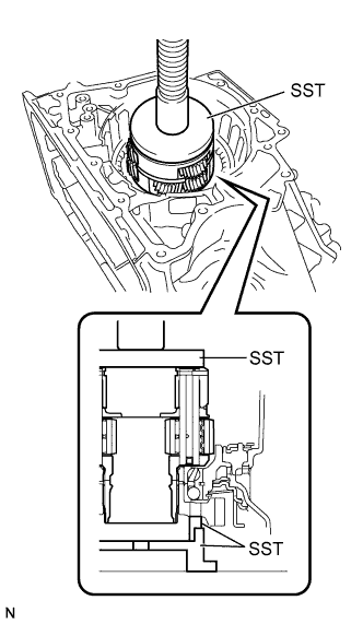
Using SST, turn the front differential case right and left 2 or 3 times to settle the bearing.
- SST
- 09564-33010
-
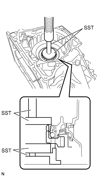
Using SST and a torque wrench, measure the turning torque of the differential side bearing while rotating SST at 10 rpm.
- SST
- 09564-33010
Standard turning torque 1.05 to 1.93 N*m (10.7 to 19.7 kgf*cm, 9.29 to 17.1 in.*lbf) If the turning torque is not within the specified range, refer to the table below to select a shim of a different thickness so that the turning torque is within the specified range, and replace the installed shim with the selected shim.
Shim Thickness Thickness Thickness Thickness Thickness 2.000 mm (0.0787 in.) 2.225 mm (0.0876 in.) 2.450 mm (0.0965 in.) 2.675 mm (0.105 in.) 2.025 mm (0.0797 in.) 2.250 mm (0.0886 in.) 2.475 mm (0.0974 in.) 2.700 mm (0.106 in.) 2.050 mm (0.0807 in.) 2.275 mm (0.0896 in.) 2.500 mm (0.0984 in.) 2.725 mm (0.107 in.) 2.075 mm (0.0817 in.) 2.300 mm (0.0906 in.) 2.525 mm (0.0994 in.) 2.750 mm (0.108 in.) 2.100 mm (0.0827 in.) 2.325 mm (0.0915 in.) 2.550 mm (0.100 in.) 2.775 mm (0.109 in.) 2.125 mm (0.0837 in.) 2.350 mm (0.0925 in.) 2.575 mm (0.101 in.) 2.800 mm (0.110 in.) 2.150 mm (0.0846 in.) 2.375 mm (0.0935 in.) 2.600 mm (0.102 in.) 2.825 mm (0.111 in.) 2.175 mm (0.0856 in.) 2.400 mm (0.0945 in.) 2.625 mm (0.103 in.) 2.850 mm (0.112 in.) 2.200 mm (0.0866 in.) 2.425 mm (0.0955 in.) 2.650 mm (0.104 in.) 2.875 mm (0.113 in.) -
Remove the 20 bolts and transaxle housing from the transaxle case.
-
Remove the front differential case from the transaxle case.
-
-
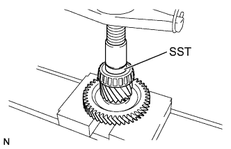
INSTALL COUNTER DRIVEN GEAR BEARING (FRONT)
-
Using SST and a press, install a new counter driven gear bearing to the counter driven gear.
- SST
- 09950-60010 ( 09951-00530 )
Note
Be sure to install the counter driven gear bearing so that there is no clearance between the bearing and the counter driven gear. If there is any clearance, the turning torque of the counter drive gear cannot be measured correctly.
-
-
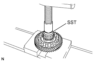
INSTALL COUNTER DRIVEN GEAR BEARING (REAR)
-
Using SST and a press, install a new counter driven gear bearing to the counter driven gear.
- SST
- 09950-60010 ( 09951-00420 )
Note
Be sure to install the counter driven gear bearing and the differential drive pinion so that there is no clearance between each of them and the counter driven gear.
-
-
ADJUST COUNTER DRIVEN GEAR BEARING PRELOAD
-
Install the counter driven gear and front differential case to the transaxle case.
-
Install the transaxle housing to the transaxle case with the 20 bolts.
- Torque:
- for bolt A
- 31 N*m { 312 kgf*cm, 23 ft.*lbf }
- for bolt B
- 23 N*m { 231 kgf*cm, 17 ft.*lbf }
-
Using SST and a torque wrench, measure the turning torque of the counter driven gear while rotating SST at 10 rpm.
- SST
- 09564-33010
Standard turning torque Front differential case bearing preload + 3.29 to 6.07 N*m (33.5 to 61.9 kgf*cm, 29.1 to 53.7 in.*lbf) If the turning torque is not within the specified range, refer to the table below to select a shim of a different thickness so that the turning torque is within the specified range, and replace the installed shim with the selected shim.
Shim Thickness Thickness Thickness Thickness Thickness 2.000 mm (0.0787 in.) 2.275 mm (0.0896 in.) 2.525 mm (0.0994 in.) 2.775 mm (0.109 in.) 2.025 mm (0.0797 in.) 2.300 mm (0.0906 in.) 2.550 mm (0.100 in.) 2.800 mm (0.110 in.) 2.050 mm (0.0807 in.) 2.325 mm (0.0915 in.) 2.575 mm (0.101 in.) 2.825 mm (0.111 in.) 2.075 mm (0.0817 in.) 2.350 mm (0.0925 in.) 2.600 mm (0.102 in.) 2.850 mm (0.112 in.) 2.100 mm (0.0827 in.) 2.375 mm (0.0935 in.) 2.625 mm (0.103 in.) 2.875 mm (0.113 in.) 2.125 mm (0.0837 in.) 2.400 mm (0.0945 in.) 2.650 mm (0.104 in.) 2.900 mm (0.114 in.) 2.150 mm (0.0846 in.) 2.425 mm (0.0955 in.) 2.675 mm (0.105 in.) 2.925 mm (0.115 in.) 2.175 mm (0.0856 in.) 2.450 mm (0.0965 in.) 2.700 mm (0.106 in.) 2.950 mm (0.116 in.) 2.200 mm (0.0866 in.) 2.475 mm (0.0974 in.) 2.725 mm (0.107 in.) 2.975 mm (0.117 in.) 2.225 mm (0.0876 in.) 2.500 mm (0.0984 in.) 2.750 mm (0.108 in.) 3.000 mm (0.118 in.) 2.250 mm (0.0886 in.) - - - -
Remove the 20 bolts and transaxle housing from the transaxle case.
-
Remove the front differential case and counter driven gear from the transaxle case.
-
-
INSTALL TRANSAXLE CASE OIL SEAL LH
-
Using SST and a hammer, tap in a new transaxle case oil seal.
- SST
- 09316-10010
- 09950-70010 ( 09951-07100 )
Standard depth -0.5 to 0.5 mm (-0.0197 to 0.0197 in.) Note
Check that the oil seal is installed in the correct direction.
-
Coat the lip of the transaxle case oil seal with MP grease.
-
-
INSTALL TRANSAXLE CASE OIL SEAL RH
-
Using SST and a hammer, tap in a new front transaxle case oil seal.
- SST
- 09316-60011 ( 09316-00011 )
Standard depth -0.5 to 0.5 mm (-0.0197 to 0.0197 in.) Note
Check that the oil seal is installed in the correct direction.
-
Coat the lip of the front transaxle case oil seal with MP grease.
-
-
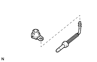
INSTALL MANUAL VALVE LEVER SHAFT OIL SEAL
-
Coat the lip of a new manual valve lever shaft oil seal with MP grease.
-
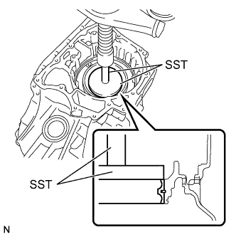
Using SST and a hammer, tap in the manual valve lever shaft oil seal to the transaxle case.
- SST
- 09950-60010 ( 09951-00230 )
- 09950-70010 ( 09951-07100 )
Standard depth -0.5 to 0.5 mm (-0.0197 to 0.0197 in.)
-
-
INSTALL MANUAL VALVE LEVER SHAFT
-
Install a new spacer to the parking lock lever.
-
Install the parking lock lever to the manual valve lever shaft.
-
Install a new spacer to the manual valve lever.
-
Install the manual valve lever to the manual valve lever shaft.
-
Install the manual valve lever shaft to the transaxle case.
Note
Do not damage the manual valve lever shaft oil seal while installing the manual valve lever shaft to the transaxle case.
-
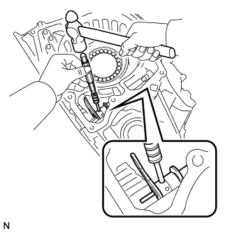
Using a 3 mm pin punch and hammer, install a new slotted spring pin to the parking lock lever.
-
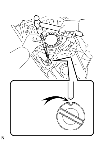
Turn the spacer and the lever shaft to align the smaller hole of the spacer with the staking position mark on the lever shaft.
-
Using a pin punch, stake the spacer through the small hole.
-
Check that the spacer does not turn.
-
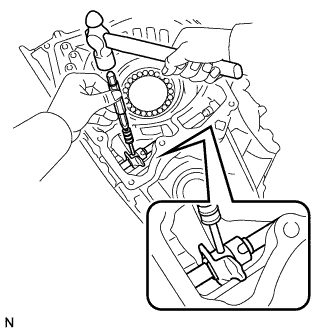
Using a 3 mm pin punch and hammer, install a new slotted spring pin to the manual valve lever.
-
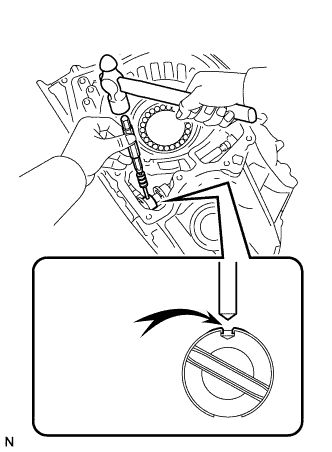
Turn the spacer and the lever shaft to align the smaller hole of the spacer with the staking position mark on the lever shaft.
-
Using a pin punch, stake the spacer through the small hole.
-
Check that the spacer does not turn.
-
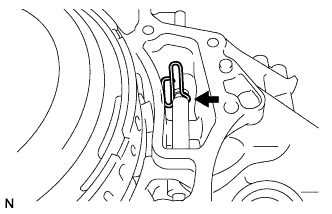
Using needle-nose pliers, install the manual valve shaft retainer spring to the transaxle case.
-
-
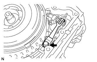
INSTALL PARKING LOCK ROD SUB-ASSEMBLY
-
Align the protrusions on the parking lock rod with the notches in the parking lock lever and install the parking lock rod.
-
-
INSTALL MANUAL DETENT SPRING SUB-ASSEMBLY
-
Install the manual detent spring and cover to the transaxle case with the bolt.
- Torque:
- 23 N*m { 231 kgf*cm, 17 ft.*lbf }
Note
Make sure to install the manual detent spring first and then the cover.
-
-
INSTALL COUNTER DRIVE GEAR BEARING
Note
Perform this procedure only when the counter drive gear bearing or transaxle case is replaced.
-
Using SST and a press, install a new counter drive gear bearing and snap ring to the transaxle case.
- SST
- 09950-60020 ( 09951-01030 )
- 09950-70010 ( 09951-07100 )
-
-
INSTALL NO. 3 BRAKE PISTON
-
Coat the contact surface of the transaxle case with ATF.
-
Coat the seal lip of the No. 3 brake piston with ATF.
-
Temporarily install the pawl stopper plate to the transaxle case with the 2 bolts.
-
Press the No. 3 brake piston into the transaxle case to install it.
Note
-
Make sure that the lip of the No. 3 brake piston is not twisted and does not get caught in the transaxle case.
-
After installing, make sure that the protrusions on the No. 3 brake piston and the grooves on the pawl stopper plate are aligned.
Tech Tips
Use the installation surface of the return spring to press the piston into the transaxle case.
-
-
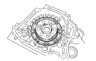
Install the return spring to the transaxle case.
-

Remove the 2 bolts and pawl stopper plate from the transaxle case.
-
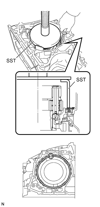
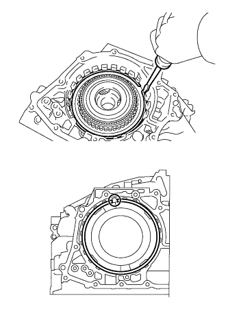
Place SST on the brake piston return spring and compress the brake piston return spring with a press.
- SST
- 09387-00070
Note
Stop the press when the brake piston return spring is flush with the snap ring groove. This prevents the brake piston return spring from being deformed.
-
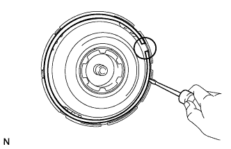
Using a screwdriver, install the snap ring to the transaxle case as shown in the illustration.
Note
-
Make sure that the snap ring is seated properly in the groove of the transaxle case.
-
Be sure to align the opening of the snap ring with one of the protrusions on the brake piston return spring as shown in the illustration.
-
-
-
INSTALL COUNTER DRIVE GEAR
-
Using SST and a press, install a new bearing inner race (front side) to the counter drive gear.
- SST
- 09387-00020
-
Using SST, install a new bearing inner race (rear side) and the counter drive gear to the transaxle case.
- SST
- 09223-15030
- 09527-17011
- 09950-60020 ( 09951-00810 )
- 09950-70010 ( 09951-07100 )
Note
Make sure that there is no clearance between the bearing inner race (front side) and counter drive gear.
-
-
INSTALL FRONT PLANETARY GEAR ASSEMBLY
-
Using SST and a press, press in the planetary gear to the transaxle case.
- SST
- 09223-15030
- 09527-17011
- 09951-01100
-
-
INSTALL NO. 2 BRAKE PISTON
-
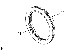
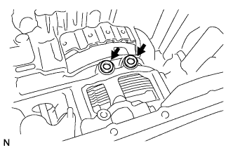
Coat 2 new O-rings with ATF and install them to the No. 2 brake piston.
Text in Illustration *1 O-Ring Note
Ensure that the 2 O-rings are not twisted.
-
Install the No. 2 brake piston to the transaxle case.
Note
Be careful not to damage the O-rings.
-
-
INSTALL 1ST AND REVERSE BRAKE RETURN SPRING SUB-ASSEMBLY
-
Install the 1st and reverse brake return spring to the transaxle case.
-
Place SST on the 1st and reverse brake return spring and compress the 1st and reverse brake return spring with a press.
- SST
- 09387-00060
Note
Stop the press when the 1st and reverse brake return spring is flush with the snap ring groove. This prevents the 1st and reverse brake return spring from being deformed.
-
Using a screwdriver, install the snap ring to the transaxle case as shown in the illustration.
Note
-
Make sure that the snap ring is seated properly in the groove of the transaxle case.
-
Be sure to align the opening of the snap ring with one of the protrusions on the transaxle case as shown in the illustration.
-
-
-
INSTALL NO. 2 BRAKE DISC
-
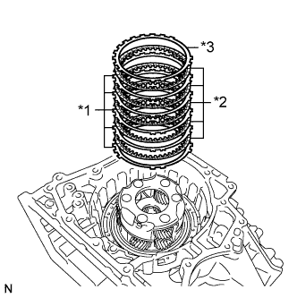
Install the 5 brake plates, 5 brake discs and brake flange to the transaxle case.
Text in Illustration *1 Brake Plate *2 Brake Disc *3 Brake Flange Note
-
Make sure that the discs, plates, and flange are installed in the correct order.
-
Before assembling new discs, soak them in ATF for at least 15 minutes.
-
-
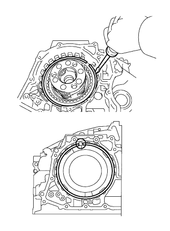
Using a screwdriver, install the snap ring to the transaxle case.
Note
-
Make sure that the snap ring is seated properly in the groove of the transaxle case.
-
Be sure to align the opening of the snap ring with one of the protrusions on the transaxle case as shown in the illustration.
-
-
-
INSPECT PISTON STROKE OF NO. 2 BRAKE
-
Using a dial indicator, measure the piston stroke of the No. 2 brake while applying compressed air (200 kPa, 2.0 kgf/cm2, 29 psi).
Standard stroke 0.884 to 1.196 mm (0.0348 to 0.0471 in.) Tech Tips
Measure the stroke at 3 points where the brake piston diameter is approximately 140 mm (5.51 in.) and calculate the average.
If the stroke is not as specified, replace the No. 2 brake flange with one of a different thickness so that the stroke is within the specified range.
Tech Tips
There are 5 flanges of different thicknesses.
Flange Thickness Mark Thickness 40 4.0 mm (0.157 in.) 41 4.1 mm (0.161 in.) 42 4.2 mm (0.165 in.) 43 4.3 mm (0.169 in.) 44 4.4 mm (0.173 in.)
-
-
INSTALL PLANETARY RING GEAR FLANGE
-
Install the planetary ring gear flange to the planetary ring gear.
-
Using a screwdriver, install the snap ring to the planetary ring gear.
Note
Make sure that the snap ring is seated properly in the groove of the planetary ring gear.
-
-
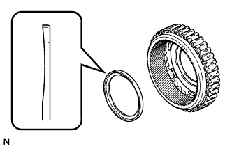
INSTALL PLANETARY RING GEAR
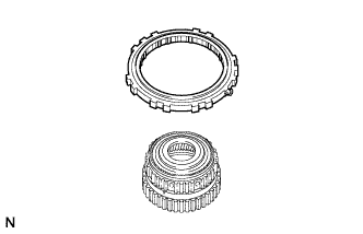
-
Install the planetary ring gear to the one-way clutch.
Note
Make sure that the one-way clutch is positioned in the correct direction as shown in the illustration.
-
-
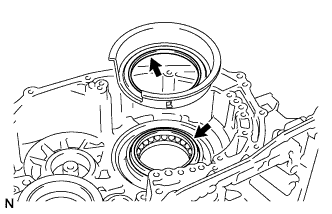
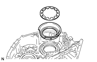
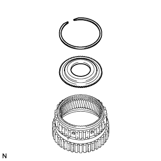
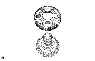
INSTALL ONE-WAY CLUTCH ASSEMBLY
-
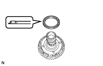
Coat the thrust needle roller bearing with ATF, and install it to the planetary gear.
Bearing Diameter Item Inside Outside Bearing 56.1 mm (2.21 in.) 80.9 mm (3.19 in.) Note
Be sure to install the thrust needle roller bearing properly so that the temper colored side of the race is visible.
-
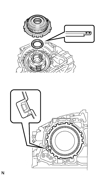
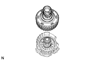
Install the one-way clutch assembly to the transaxle case.
Note
Make sure that there is no clearance between the retainer and the claw on the one-way clutch. If there is any clearance, the spring of the retainer will be deformed.
-
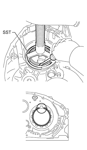
Using a screwdriver, install the snap ring to the transaxle case.
Note
-
Make sure that the snap ring is seated properly in the groove of the transaxle case.
-
Be sure to align the opening of the snap ring with one of the protrusions on the transaxle case as shown in the illustration.
-
-
-
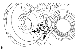
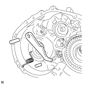
INSTALL PARKING LOCK PAWL
-
Install the parking lock pawl to the transaxle case with the parking lock pawl shaft.
-
Install the parking lock pawl pin to the transaxle case.
-
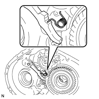
Install the spring to the parking lock pawl.
Note
Make sure that one end of the spring is fixed in the hole of the transaxle case and the other end is positioned on the parking lock pawl as shown in the illustration.
-
-
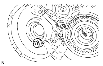
INSTALL PARKING LOCK SLEEVE
-
Install the parking lock sleeve to the transaxle case.
-
-
INSTALL PAWL STOPPER PLATE
-
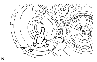
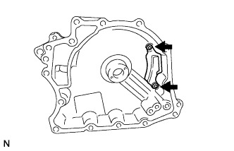
Install the pawl stopper plate to the transaxle case with the 2 bolts.
- Torque:
- 23 N*m { 231 kgf*cm, 17 ft.*lbf }
-
-
INSTALL PAWL SHAFT CLAMP
-
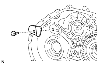
Install the pawl shaft clamp to the transaxle case with the bolt.
- Torque:
- 23 N*m { 231 kgf*cm, 17 ft.*lbf }
-
-
INSTALL COUNTER DRIVEN GEAR
-
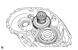
Install the counter driven gear to the transaxle case.
-
-
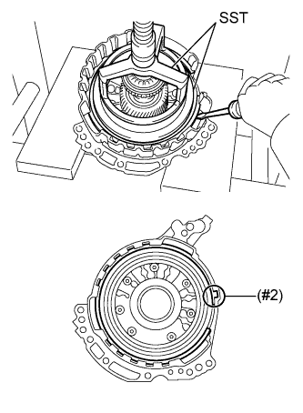
INSTALL COUNTER DRIVE GEAR NUT
-
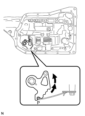
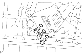
Turn the manual shaft lever 2 notches counterclockwise to set it to the P position as shown in the illustration.
-
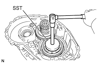
Using SST, install a new counter drive gear nut.
- SST
- 09387-00130
- Torque:
- 120 N*m { 1223 kgf*cm, 88 ft.*lbf }
-
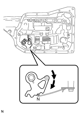
Turn the manual shaft lever 2 notches clockwise to set it to the N position as shown in the illustration.
-
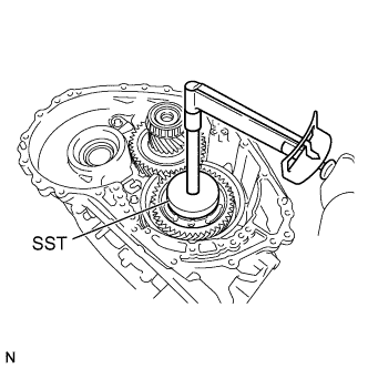
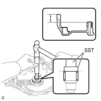
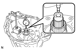
Using SST and a torque wrench, measure the turning torque of the bearing while rotating SST at 60 rpm.
- SST
- 09387-00130
Standard turning torque 0.1 to 0.22 N*m (1.02 to 2.24 kgf*cm, 0.885 to 1.95 in.*lbf) If the measured value is not within the specified range, gradually tighten the nut until the turning torque is within the specified range.
Maximum torque 180 N*m (1835 kgf*cm, 132 ft.*lbf) -
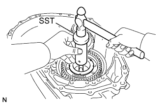
Using SST and a hammer, stake the planetary gear.
- SST
- 09930-00010
-
-
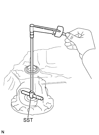
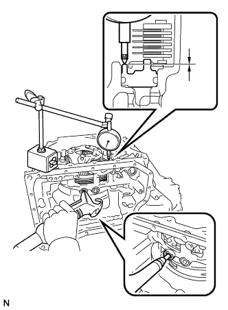
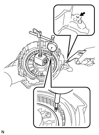
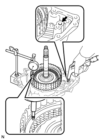
INSPECT DIFFERENTIAL SIDE GEAR BACKLASH
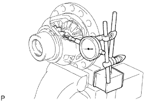
-
Hold the differential case in a vise between aluminum plates.
Note
Do not overtighten the vise.
-
Place a dial indicator at a right angle to one of the side gear teeth.
-
Hold the pinion gear in the differential case and measure the backlash of the side gear.
Standard backlash 0 to 0.15 mm (0 to 0.00591 in.) If the backlash is not within the specified range, replace both side gear thrust washers with side gear thrust washers of a different thickness.
Thrust Washer Thickness Thickness Thickness 1.50 mm (0.0591 in.) 1.75 mm (0.0689 in.) 1.55 mm (0.0610 in.) 1.80 mm (0.0709 in.) 1.60 mm (0.0630 in.) 1.85 mm (0.0728 in.) 1.65 mm (0.0650 in.) 1.90 mm (0.0748 in.) 1.70 mm (0.0669 in.) -
-
-
INSTALL FRONT DIFFERENTIAL CASE
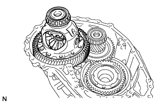
-
Install the differential case to the transaxle case.
-
-
INSTALL NO. 1 BRAKE PISTON
-
Text in Illustration *1 O-Ring Coat 2 new O-rings with ATF and install them to the No. 1 brake piston.
Note
Ensure that the O-rings are not twisted.
-
Install the No. 1 brake piston to the oil pump.
Note
Be careful not to damage the O-rings.
-
-
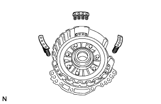
INSTALL 2ND BRAKE PISTON RETURN SPRING SUB-ASSEMBLY
-
Install the 3 2nd brake piston return springs to the oil pump.
Note
Make sure that the 3 2nd brake piston return springs are installed to the protrusions on the oil pump.
-
-
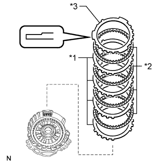
INSTALL NO. 1 BRAKE DISC
-
Install the 4 brake plates, 4 brake discs and brake flange to the oil pump.
Text in Illustration *1 No. 1 Brake Plate *2 No. 1 Brake Disc *3 No. 1 Brake Flange Note
-
Make sure that the discs, plates, and flange are installed in the correct order.
-
Be sure to install the flange in the correct direction.
-
Before assembling new discs, soak them in ATF for at least 15 minutes.
-
-
Place SST on the flange and compress the flange with a press.
- SST
- 09387-00070
- 09495-65040
Note
Stop the press when the brake piston return spring is flush with the snap ring groove. This prevents the brake piston return spring from being deformed.
-
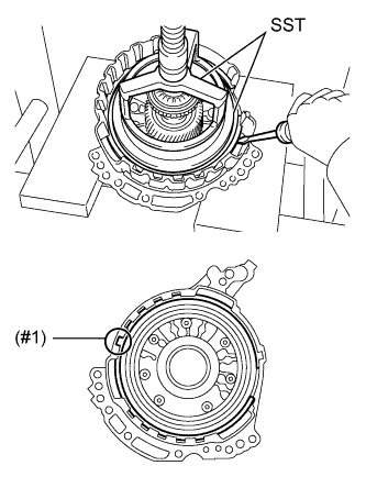
Using a screwdriver, install the snap ring to the oil pump as shown in the illustration.
Note
-
Make sure that the snap ring is seated properly in the groove of the oil pump.
-
Make sure to align the protruding part of the snap ring with the indented part (#1) of the front oil pump and gear body as shown in the illustration to install the snap ring.
-
-
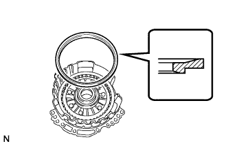
Install the brake snap ring stopper to the oil pump.
Note
Be sure to install the brake snap ring stopper in the correct direction.
-
Using a screwdriver, install the snap ring to the oil pump as shown in the illustration.
Note
-
Make sure that the snap ring is seated properly in the groove of the oil pump.
-
Make sure to align the protruding part of the snap ring with the indented part (#2) of the front oil pump and gear body as shown in the illustration to install the snap ring.
-
-
Text in Illustration *1 Snap Ring *2 Brake Snap Ring Stopper Check that the brake snap ring stopper can be turned by hand.
If the brake snap ring stopper cannot be turned by hand, the brake snap ring stopper may have been installed upside down, or the snap ring may not have been completely located in the groove on the oil pump. Remove and reinstall the snap ring and the brake snap ring stopper.
-
-
INSPECT PISTON STROKE OF NO. 1 BRAKE
-
Using a dial indicator, measure the piston stroke of the No. 1 brake while applying compressed air (200 kPa, 2.0 kgf/cm2, 29 psi).
Standard stroke 0.807 to 0.974 mm (0.0318 to 0.0383 in.) Tech Tips
Measure the stroke at 3 points where the brake piston diameter is approximately 140 mm (5.51 in.) and calculate the average.
If the stroke is not as specified, replace the No. 1 brake flange with one of a different thickness so that the stroke is within the specified range.
Tech Tips
There are 6 flanges of different thicknesses.
Flange Thickness Mark Thickness 30 3.0 mm (0.118 in.) 31 3.1 mm (0.122 in.) 32 3.2 mm (0.126 in.) 33 3.3 mm (0.130 in.) 34 3.4 mm (0.134 in.) 35 3.5 mm (0.138 in.)
-
-
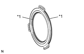
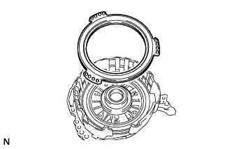
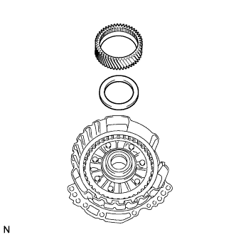
INSTALL UNDERDRIVE PLANETARY SUN GEAR
-
Coat the thrust needle roller bearing with ATF, and install it to the oil pump.
Bearing Diameter Item Inside Outside Bearing 57.7 mm (2.27 in.) 75.2 mm (2.96 in.) Note
Be sure to install the thrust needle roller bearing properly so that the temper colored side of the race is visible.
-
Install the underdrive planetary sun gear to the oil pump.
-
-
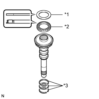
INSTALL INPUT SHAFT SUB-ASSEMBLY
-
Coat 3 new input shaft oil seal rings with ATF and install them to the input shaft.
Note
Do not expand the gaps of the oil seal rings too much.
-
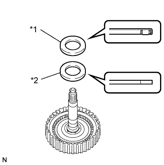
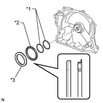
Coat the thrust needle roller bearing and thrust needle roller bearing race with ATF, and install them to the oil pump.
Bearing Diameter Item Inside Outside Bearing 29.1 mm (1.15 in.) 48.6 mm (1.91 in.) Race 30.7 mm (1.21 in.) 48.3 mm (1.90 in.) Text in Illustration *1 Thrust Needle Roller Bearing Race *2 Thrust Needle Roller Bearing *3 Input Shaft Oil Seal Ring Note
Be sure to install the thrust needle roller bearing in the correct direction.
-
Install the input shaft to the oil pump.
-
-
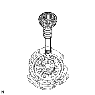
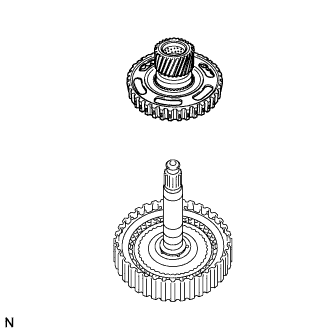
INSTALL PLANETARY SUN GEAR SUB-ASSEMBLY
-
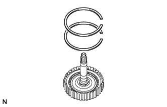
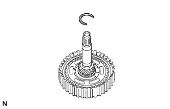
Using a snap ring expander, install the planetary sun gear and snap ring to the underdrive planetary gear.
-
-
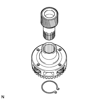
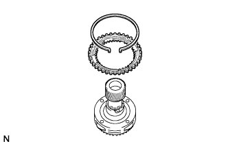
INSTALL UNDERDRIVE PLANETARY RING GEAR
-
Install the underdrive planetary ring gear to the underdrive planetary gear.
-
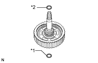
Using needle-nose pliers, install the snap ring to the underdrive planetary ring gear.
Note
Make sure that the snap ring is seated properly in the groove of the underdrive planetary ring gear.
-
-
INSTALL NO. 3 BRAKE HUB
-
Coat the thrust needle roller bearing with ATF and install it to the underdrive planetary gear.
Bearing Diameter Item Inside Outside Bearing 62.6 mm (2.46 in.) 82.9 mm (3.26 in.) Note
Be sure to install the thrust needle roller bearing properly so that the temper colored side of the race is visible.
-
Coat the thrust needle roller bearing race with MP grease and install it to the No. 3 brake hub.
Bearing Diameter Item Inside Outside Race 65.9 mm (2.59 in.) 80.3 mm (3.16 in.) -
Install the No. 3 brake hub to the underdrive planetary gear.
-
-
INSTALL UNDERDRIVE PLANETARY GEAR ASSEMBLY
-
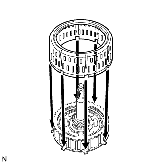
Install the underdrive planetary gear to the oil pump.
-
-
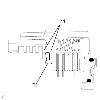
INSTALL NO. 3 BRAKE DISC
-
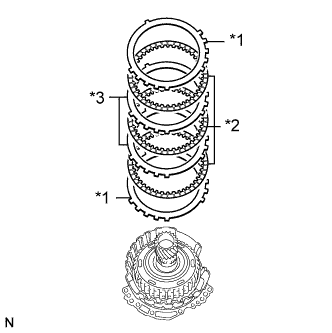
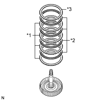
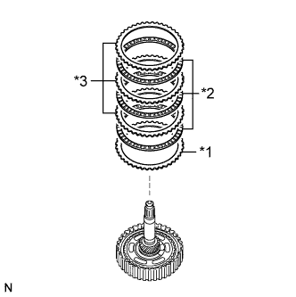
Install the 2 brake flanges, 3 brake discs and 2 brake plates to the oil pump.
Text in Illustration *1 No. 3 Brake Flange *2 No. 3 Brake Disc *3 No. 3 Brake Plate Note
-
Make sure that the discs, plates, and flanges are installed in the correct order.
-
Before assembling new discs, soak them in ATF for at least 15 minutes.
-
-
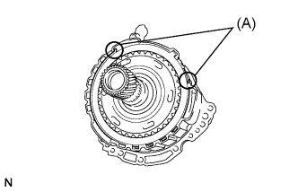
Using a screwdriver, install the snap ring to the oil pump.
Note
-
Make sure the snap ring is seated properly in the groove of the oil pump.
-
Make sure that the snap ring ends are positioned as shown in the illustration (A).
-
-
-
INSPECT CLEARANCE OF NO. 3 BRAKE
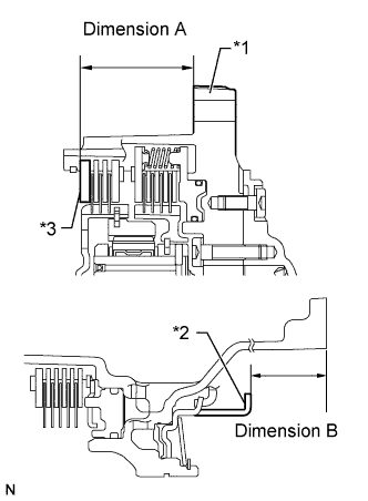
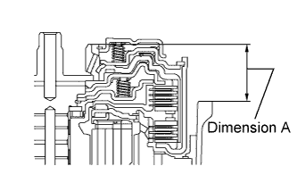
Text in Illustration *1 Front Oil Pump Assembly *2 No. 3 Brake Piston
-
Using a vernier caliper and straightedge, measure the distance shown in the illustration (dimension A) while a load of 500 N (51 kgf, 112 lbf) is being applied to the flange.
Tech Tips
Measure dimension A at 3 points where the flange diameter is approximately 166 mm (6.54 in.) and calculate the average.
-
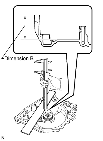
Using a vernier caliper and straightedge, measure the distance from the contact surface of the front oil pump to the end of the No. 3 brake piston shown in the illustration (dimension B).
Tech Tips
Measure dimension B at 3 points where the No. 3 brake diameter is approximately 166 mm (6.54 in.) and calculate the average.
-
Calculate the clearance value using the following formula:
Clearance = Dimension B - Dimension A
Standard clearance 0.599 to 0.761 mm (0.0236 to 0.0300 in.) If the clearance is not as specified, replace the No. 3 brake flange with one of a different thickness so that the clearance is within the specified range.
Tech Tips
There are 6 flanges of different thicknesses.
Flange Thickness Mark Thickness 38 3.80 mm (0.150 in.) 39 3.90 mm (0.154 in.) 40 4.00 mm (0.157 in.) 41 4.10 mm (0.161 in.) 42 4.20 mm (0.165 in.) 43 4.30 mm (0.169 in.)
-
-
INSTALL FRONT OIL PUMP AND GEAR BODY SUB-ASSEMBLY
-
Coat a new O-ring with ATF and install it to the transaxle case.
-
Coat the thrust needle roller bearing and thrust needle roller bearing race with ATF and install them to the counter drive gear nut.
Bearing and Race Diameter Item Inside Outside Bearing 53.1 mm (2.09 in.) 79 mm (3.11 in.) Race 59.4 mm (2.34 in.) 77 mm (3.03 in.) Text in Illustration *1 Thrust Needle Roller Bearing Race *2 Thrust Needle Roller Bearing *3 O-ring Note
Be sure to install the thrust needle roller bearing properly so that the temper colored side of the race is visible.
-
Coat a new O-ring with ATF and install it to the oil pump.
-
Install the oil pump to the transaxle case with the 7 bolts.
- Torque:
- 23 N*m { 231 kgf*cm, 17 ft.*lbf }
-
-
INSTALL DIFFERENTIAL GEAR LUBE APPLY TUBE
-
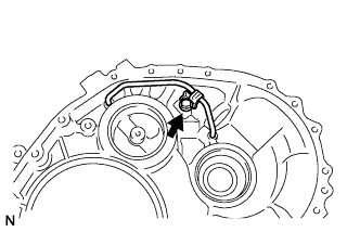
Install the differential gear lube apply tube to the transaxle housing.
Note
Insert the differential gear lube apply tube into the transaxle case until it makes contact with the stopper.
-
Install the clamp to the differential gear lube apply tube with the bolt.
- Torque:
- 23 N*m { 231 kgf*cm, 17 ft.*lbf }
Note
Make sure there is clearance between the differential lube apply tube and clamp.
-
-
INSTALL TRANSAXLE HOUSING
-
Remove any old seal packing material from the contact surfaces between the transaxle housing and case.
Note
Make sure that there is no ATF on the contact surfaces.
-
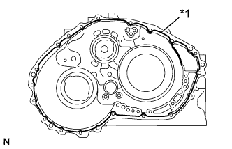
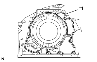
Text in Illustration *1 Seal Packing Apply seal packing to the transaxle case.
Seal packing Toyota Genuine Seal Packing 1281, Three Bond 1281 or equivalent Note
Apply seal packing in a continuous line (width 1.2 mm (0.0472 in.)) along the sealing surface.
-
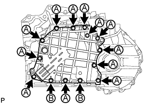
Install the transaxle housing to the transaxle case with the 20 bolts.
- Torque:
- for bolt A
- 31 N*m { 312 kgf*cm, 23 ft.*lbf }
- for bolt B
- 23 N*m { 231 kgf*cm, 17 ft.*lbf }
-
-
INSTALL NO. 1 CLUTCH DISC
-
Install the 4 clutch plates, 4 clutch discs and clutch flange to the direct multiple disc clutch.
Text in Illustration *1 Clutch Plate *2 Clutch Disc *3 Clutch Flange Note
-
Make sure that the flange, discs, and plates are installed in the correct order.
-
Before assembling new discs, soak them in ATF for at least 15 minutes.
-
-
Using a screwdriver, install the 2 snap rings to the direct multiple disc clutch.
Note
Make sure that the snap rings are seated properly in the groove of the direct multiple disc clutch.
-
-
INSPECT PISTON STROKE OF NO. 1 CLUTCH DISC
-
Install the direct multiple disc clutch to the rear transaxle cover.
-
Using a dial indicator, measure the piston stroke of the No. 1 clutch while applying and releasing compressed air (200 kPa, 2.0 kgf/cm2, 29 psi).
Tech Tips
Measure the stroke at 3 points where the flange diameter is approximately 152 mm (5.98 in.) and calculate the average.
Standard stroke 0.806 to 0.974 mm (0.0317 to 0.0383 in.) If the stroke is not as specified, replace the No. 1 clutch flange with one of a different thickness so that the stroke is within the specified range.
Tech Tips
There are 6 flanges of different thicknesses.
Flange Thickness Mark Thickness 30 3.0 mm (0.118 in.) 31 3.1 mm (0.122 in.) 32 3.2 mm (0.126 in.) 33 3.3 mm (0.130 in.) 34 3.4 mm (0.134 in.) 35 3.5 mm (0.138 in.)
-
-
INSTALL REAR PLANETARY SUN GEAR ASSEMBLY
-
Coat the thrust needle roller bearing and thrust needle roller bearing race with ATF, and install them to the direct multiple disc clutch.
Bearing and Race Diameter Item Inside Outside Bearing 28 mm (1.10 in.) 47.1 mm (1.85 in.) Race 26.1 mm (1.03 in.) 44 mm (1.73 in.) Text in Illustration *1 Thrust Needle Roller Bearing *2 Thrust Needle Roller Bearing Race Note
Install the thrust needle roller bearing properly so that the temper colored side of the race is visible.
-
Install the rear planetary sun gear to the direct multiple disc clutch.
-
Using a snap ring expander, install the snap ring to the direct multiple disc clutch.
-
-
INSTALL NO. 2 CLUTCH DISC
Text in Illustration *1 Clutch Flange *2 Clutch Disc *3 Clutch Plate
-
Install the clutch flange, 3 clutch discs and 3 clutch plates to the direct multiple disc clutch.
Note
-
Make sure that the discs, plates, and flange are installed in the correct order.
-
Before assembling new discs, soak them in ATF for at least 15 minutes.
-
-
-
INSTALL DIRECT MULTIPLE DISC CLUTCH SNAP RING
-
Coat a new O-ring with ATF and install it to the direct multiple disc clutch.
-
Coat a new intermediate shaft oil seal with ATF and install it to the intermediate shaft.
Text in Illustration *1 Intermediate Shaft Oil Seal *2 O-Ring -
Install the No. 2 direct clutch piston to the direct multiple disc clutch.
Note
Be sure to attach the claws on the direct multiple disc clutch in the grooves on the No. 2 direct clutch piston.
-
Using a screwdriver, install the snap ring to the direct multiple disc clutch.
Note
-
Position the opening of the snap ring as shown in the illustration.
-
Make sure the snap ring is seated properly in the groove of the direct multiple disc clutch.
-
-
-
INSPECT PISTON STROKE OF NO. 2 CLUTCH
-
Install the direct multiple disc clutch assembly to the rear transaxle cover sub-assembly.
-
Using a dial indicator, measure the piston stroke of the No. 2 clutch while applying and releasing compressed air (200 kPa, 2.0 kgf/cm2, 29 psi).
Tech Tips
Measure the stroke at 3 points where the diameter of the No. 2 direct multiple clutch piston is approximately 152 mm (5.98 in.) and calculate the average.
Standard stroke 0.544 to 0.744 mm (0.0214 to 0.0293 in.) If the stroke is not as specified, replace the No. 2 clutch flange with one of a different thickness so that the stroke is within the specified range.
Tech Tips
There are 6 flanges of different thicknesses.
Flange Thickness Mark Thickness 30 3.0 mm (0.118 in.) 31 3.1 mm (0.122 in.) 32 3.2 mm (0.126 in.) 33 3.3 mm (0.130 in.) 34 3.4 mm (0.134 in.) 35 3.5 mm (0.138 in.)
-
-
INSTALL DIRECT MULTIPLE DISC CLUTCH ASSEMBLY
-
Coat the thrust needle roller bearing with ATF and install it to the transaxle case.
Bearing Diameter Item Inside Outside Bearing 61.2 mm (2.41 in.) 79 mm (3.11 in.) -
Install the direct multiple disc clutch to the transaxle case.
Text in Illustration *1 Thrust Needle Roller Bearing *2 Direct Multiple Disc Clutch Assembly -
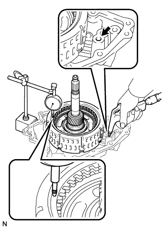
Clean the contact surfaces of the transaxle case and rear transaxle cover.
-
Place a straightedge on the direct multiple disc clutch and measure the distance between the transaxle case and the straightedge using a vernier caliper (Dimension A in the illustration).
-
Using a vernier caliper and a straightedge, measure the distance shown in the illustration (Dimension B).
-
Calculate the end play value using the following formula:
End play = Dimension B - Dimension A
Standard end play 0.007 to 1.113 mm (0.000275 to 0.0438 in.)
-
-
INSTALL REAR TRANSAXLE COVER SUB-ASSEMBLY
-
Using SST and a hammer, install the needle roller bearing to the rear transaxle cover.
- SST
- 09950-60010 ( 09951-00220 )
- 09950-70010 ( 09951-07100 )
Installation depth 21.5 to 21.9 mm (0.846 to 0862 in.) -
Apply adhesive to the 2 screws.
Adhesive Toyota Genuine Adhesive 1324, Three Bond 1324 or equivalent -
Using a T30 "TORX" wrench, install the rear transaxle cover plate to the rear transaxle cover with the 2 screws.
- Torque:
- 7.5 N*m { 76 kgf*cm, 66 in.*lbf }
-
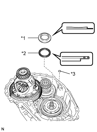
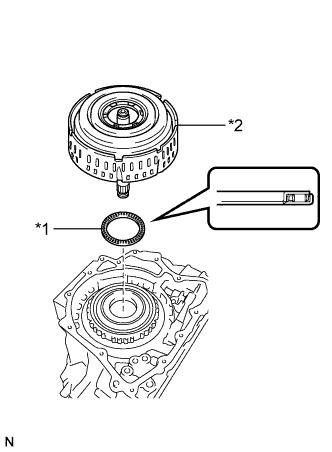
Text in Illustration *1 Oil Seal Ring *2 Thrust Needle Roller Bearing *3 Thrust Needle Roller Bearing Race Coat the thrust needle roller bearing and thrust needle roller bearing race with ATF and install them to the transaxle case.
Bearing Diameter Item Inside Outside Bearing 48.9 mm (1.93 in.) 72.0 mm (2.84 in.) Race 52.2 mm (2.06 in.) 70.4 mm (2.77 in.) -
Coat 2 new oil seal rings with ATF and install them to the rear transaxle cover.
-
Coat the 3 new O-rings with ATF and install them to the transaxle case.
Note
Ensure that the O-rings are not twisted.
-
Remove any old seal packing material from the contact surfaces between the rear transaxle cover and transaxle case.
-
Apply seal packing to the transaxle case.
Note
Make sure that there is no ATF on the contact surfaces.
Seal packing Toyota Genuine Seal Packing 1281, Three Bond 1281 or equivalent -
Install the rear transaxle cover to the transaxle case with the 14 bolts.
- Torque:
- Bolt A
- 23 N*m { 231 kgf*cm, 17 ft.*lbf }
- Bolt B
- 17 N*m { 172 kgf*cm, 12 ft.*lbf }
-
Install a new gasket to the refill plug.
-
Install the refill plug to the rear transaxle cover.
- Torque:
- 49 N*m { 500 kgf*cm, 36 ft.*lbf }
-
Coat 3 new O-rings with ATF and install them to the 3 No. 1 automatic transaxle case plugs.
-
Install the 3 No. 1 automatic transaxle case plugs to the rear transaxle cover.
- Torque:
- 7.4 N*m { 75 kgf*cm, 65 in.*lbf }
-
-
INSPECT INPUT SHAFT END PLAY
-
Using a dial indicator, measure the input shaft end play.
Standard end play 0.012 to 1.250 mm (0.000473 to 0.0492 in.)
-
-
INSTALL TRANSAXLE CASE GASKET
-
Coat 2 new gaskets with ATF and install them to the transaxle case.
-
-
INSTALL TRANSMISSION VALVE BODY ASSEMBLY
-
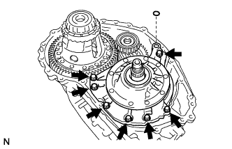
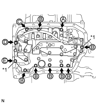
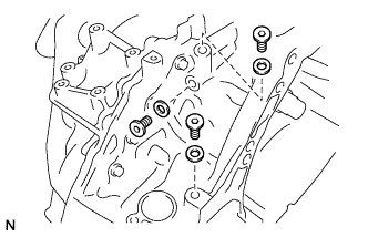
Install the valve body to the transaxle case with the 11 bolts.
- Torque:
- 11 N*m { 110 kgf*cm, 8 ft.*lbf }
Note
-
When installing the transmission valve body, be careful not to allow the transmission revolution sensor and transaxle case to interfere with each other.
-
Be sure to insert the pin of the manual valve lever into the groove on the end of the manual valve.
-
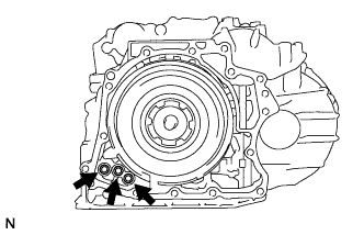
Temporarily install the bolts marked by *1 in the illustration first because they are positioning bolts.
Tech Tips
Each bolt length is indicated below.
for bolt A: 25 mm (0.984 in.)
for bolt B: 30 mm (1.18 in.)
for bolt C: 35 mm (1.38 in.)
for bolt D: 45 mm (1.77 in.)
for bolt E: 55 mm (2.17 in.)
-
-
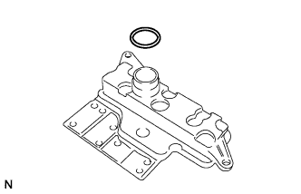
INSTALL VALVE BODY OIL STRAINER ASSEMBLY
-
Coat a new O-ring with ATF and install it to the oil strainer.
Note
Ensure that the O-ring is not twisted or pinched.
-
Install the oil strainer to the valve body with the 2 bolts.
- Torque:
- 11 N*m { 110 kgf*cm, 8 ft.*lbf }
-
-
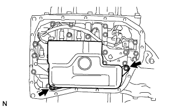
INSTALL AUTOMATIC TRANSAXLE OIL PAN SUB-ASSEMBLY
-
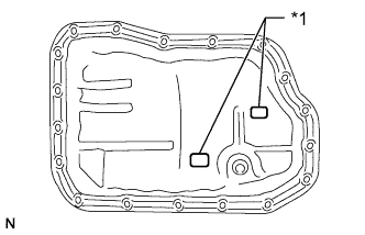
Install the 2 magnets in the automatic transaxle oil pan.
Text in Illustration *1 Magnet -
Install a new gasket to the oil pan.
-
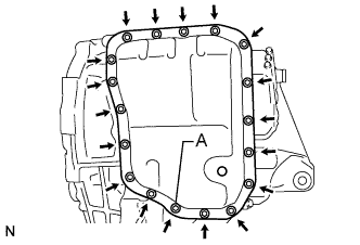
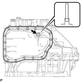
Apply seal packing to the bolt labeled A in the illustration.
Seal packing Toyota Genuine Seal Packing 1281, Three Bond 1281 or equivalent -
Install the oil pan to the automatic transaxle with the 18 bolts.
- Torque:
- for bolt labeled A
- 7.0 N*m { 71 kgf*cm, 62 in.*lbf }
- for other bolt
- 7.5 N*m { 76 kgf*cm, 66 in.*lbf }
Note
-
In order to ensure proper sealing of the transmission oil pan bolt, apply seal packing to the bolt and install it within 10 minutes of seal packing application.
-
Completely remove any oil or grease from the contact surfaces of the transaxle case, oil pan sub-assembly and gasket before installation.
-
Using a 6 mm hexagon wrench, install the No. 1 transmission oil filler tube to the automatic transaxle.
- Torque:
- 1.7 N*m { 17 kgf*cm, 15 in.*lbf }
-
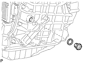
Using a 6 mm hexagon wrench, install the a new gasket and the overflow plug to the oil pan.
- Torque:
- 40 N*m { 408 kgf*cm, 30 ft.*lbf }
-
-
INSTALL NO. 1 TRANSAXLE CASE PLUG
-
Install 3 new gaskets to the 3 transaxle case plugs.
-
Apply adhesive to the 3 transaxle case plugs.
Adhesive Toyota Genuine Seal Packing 1324, Three Bond 1324 or equivalent Note
In order to ensure proper sealing of the transaxle case plugs, apply adhesive to the plugs and install them within 10 minutes of adhesive application.
-
Using a 6 mm hexagon wrench, install the 3 gaskets and 3 transaxle case plug to the transaxle housing.
- Torque:
- 17 N*m { 173 kgf*cm, 12 ft.*lbf }
-
Coat 3 new O-rings with ATF and install them to the 3 transaxle case plugs.
-
Install the 3 transaxle case plugs to the transaxle case.
- Torque:
- 7.4 N*m { 75 kgf*cm, 65 in.*lbf }
-
-
INSTALL OIL COOLER TUBE UNION (INLET)
-
Coat a new O-ring with ATF and install it to the oil cooler tube union (inlet).
-
Install the oil cooler tube union (inlet) to the transaxle case.
- Torque:
- 27 N*m { 275 kgf*cm, 20 ft.*lbf }
-
-
INSTALL OIL COOLER TUBE UNION (OUTLET)
-
Coat a new O-ring with ATF and install it to the oil cooler tube union (outlet).
-
Install the oil cooler tube union (outlet) to the transaxle case as shown in the illustration.
- Torque:
- 27 N*m { 275 kgf*cm, 20 ft.*lbf }
-
-
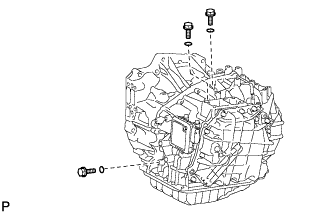
INSTALL PARK/NEUTRAL POSITION SWITCH ASSEMBLY
-
Install the park/neutral position switch to the control shaft.
-
Temporarily install the 2 bolts.
-
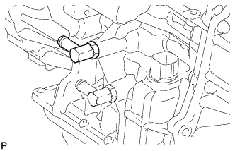
Temporarily install the control shaft lever.
-
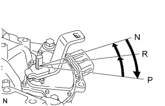
Turn the lever clockwise until it stops, and then turn it counterclockwise 2 notches.
-
Remove the control shaft lever.
-
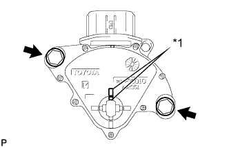
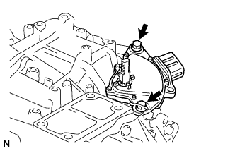
Align the protrusions of the park/neutral position switch.
-
Hold the switch in that position and tighten the 2 bolts.
- Torque:
- 5.4 N*m { 55 kgf*cm, 48 in.*lbf }
Text in Illustration *1 Protrusion -
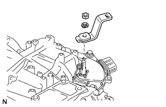
Install the control shaft lever to the control shaft with the washer and nut.
- Torque:
- 13 N*m { 130 kgf*cm, 9 ft.*lbf }
-
-
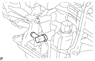
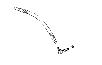
INSTALL BREATHER PLUG HOSE
-
Coat a new O-ring with ATF and install it to the breather plug.
-
Install the breather plug to the breather plug hose.
-
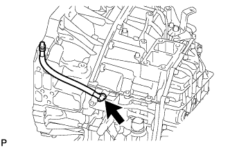
Install the breather plug hose to the transaxle case.
-