AUTOMATIC TRANSAXLE ASSEMBLY INSTALLATION

-
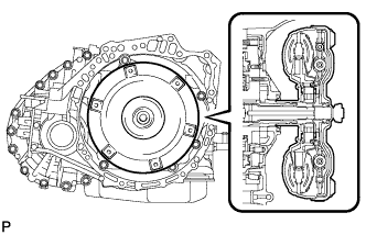
INSTALL TORQUE CONVERTER CLUTCH ASSEMBLY
-
Mesh the splines of the input shaft and turbine runner.
-
Mesh the splines of the stator shaft and stator while turning torque converter clutch.
Tech Tips
If the stator shaft splines are difficult to mesh with the stator splines, move the torque converter clutch back approximately 10 mm (0.394 in.) and mesh the splines while rotating the torque converter clutch.
-
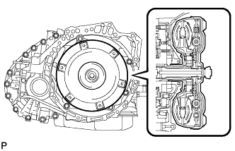
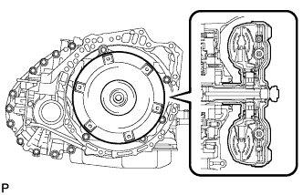
Turn the torque converter clutch to insert the key of the oil pump drive gear into the slot in the torque converter clutch.
-
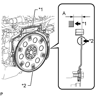
Using a vernier caliper and straightedge, measure dimension A between the transaxle fitting surface of the engine*1 and the converter clutch fitting surface of the drive plate*2. (#)
-
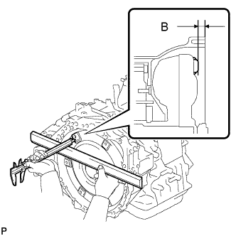
Using a vernier caliper and straightedge, measure dimension B shown in the illustration. Check that B is more than A (measured in (#)).
Standard distance B = A + 1 mm (0.0394 in.) or more Note
If the transaxle is installed to the engine with the torque converter clutch not sufficiently inserted, the torque converter clutch may be damaged.
-
-
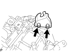
INSTALL TCM
-
Install the TCM to the transaxle.
-
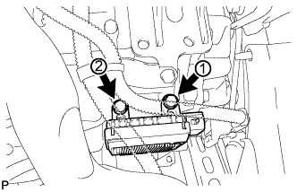
Install and tighten the 2 bolts in the order shown in the illustration.
- Torque:
- 11 N*m { 115 kgf*cm, 8 ft.*lbf }
-
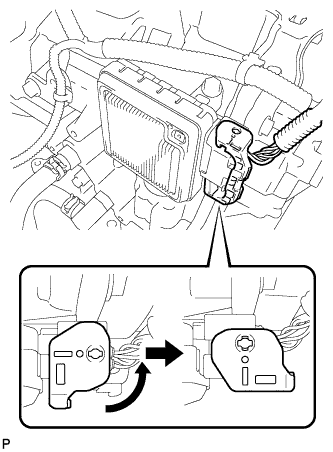
Connect the connector to the TCM.
-
Turn the lock lever until the claw of the connector makes a connection sound and secure the connector with the lock lever.
-
-
INSTALL SPEEDOMETER DRIVEN HOLE COVER SUB-ASSEMBLY
-
Coat a new O-ring with ATF and install it to the speedometer driven hole cover.
-
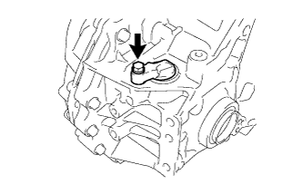
Install the speedometer driven hole cover with the bolt.
- Torque:
- 5.5 N*m { 56 kgf*cm, 49 in.*lbf }
-
-
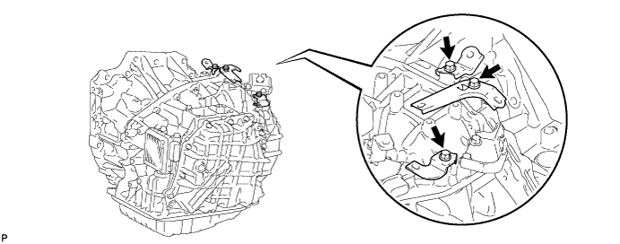
INSTALL NO. 1 TRANSMISSION CONTROL CABLE BRACKET
-
Install the No. 1 transmission control cable bracket with the 2 bolts.
- Torque:
- 12 N*m { 122 kgf*cm, 9 ft.*lbf }
-
-
INSTALL WIRE HARNESS CLAMP BRACKET
-
Install the 2 wire harness clamp brackets and air tube support with the 3 bolts.
- Torque:
- for air tube support
- 27 N*m { 275 kgf*cm, 20 ft.*lbf }
- for wire harness clamp bracket
- 13 N*m { 130 kgf*cm, 9 ft.*lbf }
-
-
INSTALL AUTOMATIC TRANSAXLE ASSEMBLY
-
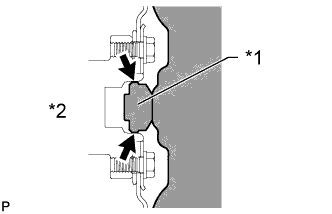
Apply clutch spline grease to the surface of the torque converter centerpiece that contacts the crankshaft.
Text in Illustration *1 Torque Converter Clutch Centerpiece *2 Crankshaft Clutch spline grease Toyota Genuine Clutch Spline Grease or equivalent Maximum grease amount Approximately 1 g (0.0353 oz.) -
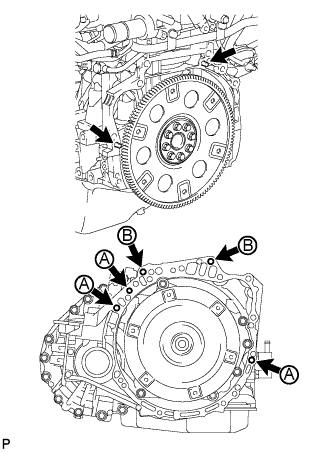
Confirm that the 2 knock pins are on the surface of the engine block that contacts the transaxle.
-
Maintain the engine and transaxle in a horizontal position, align the knock pins with each hole in the transaxle and install the transaxle with the 5 bolts shown in the illustration.
- Torque:
- for bolt A
- 46 N*m { 469 kgf*cm, 34 ft.*lbf }
- for bolt B
- 64 N*m { 653 kgf*cm, 47 ft.*lbf }
-
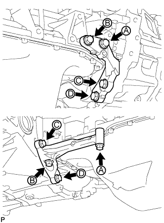
Temporarily install the stiffener plate LH and RH with the 8 bolts.
-
While holding one stiffener plate against the transaxle, tighten bolt A, and then tighten bolts B, C and D. Perform the same procedure for the other stiffener plate.
- Torque:
- 46 N*m { 469 kgf*cm, 34 ft.*lbf }
-
-
INSTALL DRIVE PLATE AND TORQUE CONVERTER CLUTCH SETTING BOLT
-
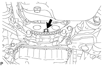
Turn the crankshaft to gain access to the installation locations of the 6 torque converter clutch setting bolts and install each bolt while holding the crankshaft pulley bolt with a wrench.
- Torque:
- 44 N*m { 449 kgf*cm, 32 ft.*lbf }
Note
Install the black bolt first, and then the 5 silver bolts.
-
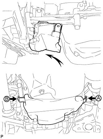
Install the oil pan insulator and temporarily install the 2 bolts.
-
Tighten bolt A, and then tighten bolt B.
- Torque:
- 9.0 N*m { 92 kgf*cm, 80 in.*lbf }
-
-
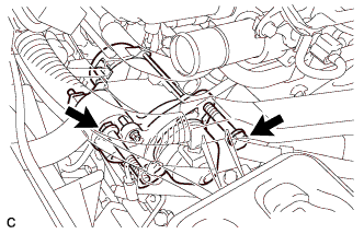
INSTALL NO. 1 AIR TUBE
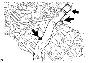
-
Install the No. 1 air tube with the 2 bolts and tighten the clamp.
- Torque:
- for bolt
- 20 N*m { 204 kgf*cm, 15 ft.*lbf }
- for clamp
- 6.5 N*m { 66 kgf*cm, 58 in.*lbf }
Note
Before installation, remove any oil residue from the inside of the tube and hose.
-
-
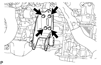
INSTALL ENGINE MOUNTING BRACKET LH
-
Install the engine mounting bracket LH to the transaxle with the 4 bolts.
- Torque:
- 64 N*m { 653 kgf*cm, 47 ft.*lbf }
-
Install the wire harness clamp bracket to the engine mounting bracket with the bolt.
- Torque:
- 8.4 N*m { 85 kgf*cm, 74 in.*lbf }
-
-
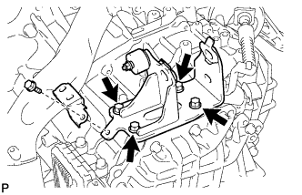
INSTALL REAR ENGINE MOUNTING BRACKET
-
Install the rear engine mounting bracket to the transaxle with the 4 bolts.
- Torque:
- 45 N*m { 459 kgf*cm, 33 ft.*lbf }
-
-
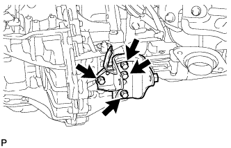
INSTALL FRONT ENGINE MOUNTING BRACKET
-
Install the front engine mounting bracket to the transaxle with the 4 bolts.
- Torque:
- 64 N*m { 653 kgf*cm, 47 ft.*lbf }
-
-
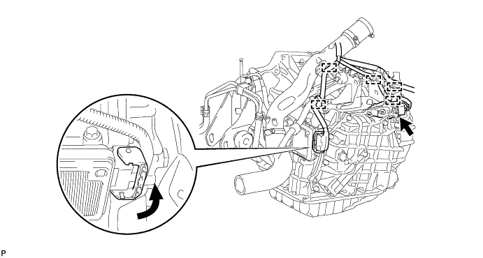
INSTALL NO. 1 OIL COOLER TUBE SUB-ASSEMBLY
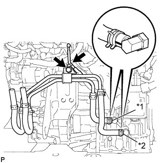
Text in Illustration *1 Yellow Paint Mark *2 White Paint Mark
-
Install the No. 1 oil cooler tube with 2 oil cooler hoses with the bolt.
- Torque:
- 12 N*m { 117 kgf*cm, 8 ft.*lbf }
-
Connect the 2 oil cooler hoses to the transaxle and connect the breather plug hose to the No. 1 oil cooler tube.
Note
Make sure the paint marks and pinching portion of each clip are facing the direction shown in the illustration.
-
-
INSTALL GROUND CABLE
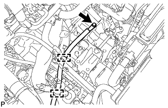
-
Install the ground cable to the transaxle with the bolt and attach the 2 clamps.
- Torque:
- 13 N*m { 130 kgf*cm, 9 ft.*lbf }
-
-
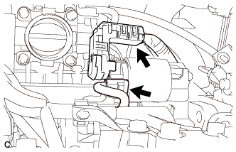
CONNECT WIRE HARNESS
-
Connect the park/neutral position switch connector and TCM connector, and attach the 5 wire harness clamps to the transaxle.
Tech Tips
Turn the lock lever until the claw of the TCM connector makes a connection sound and secure the connector with lock lever.
-
-
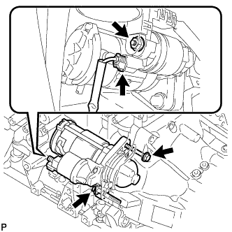
INSTALL STARTER ASSEMBLY (for DENSO Made)
-
Install the starter assembly with the 2 bolts.
- Torque:
- 64 N*m { 653 kgf*cm, 47 ft.*lbf }
-
Connect the starter wire with the nut and close the terminal cap.
- Torque:
- 9.8 N*m { 100 kgf*cm, 87 in.*lbf }
-
Connect the starter connector.
-
-
INSTALL STARTER ASSEMBLY (for VALEO Made)
-
Install the starter assembly with the 2 bolts.
- Torque:
- 64 N*m { 653 kgf*cm, 47 ft.*lbf }
-
Connect the starter wire with the nut and close the terminal cap.
- Torque:
- 9.8 N*m { 100 kgf*cm, 87 in.*lbf }
-
Connect the starter connector.
-
-
INSTALL ENGINE ASSEMBLY WITH TRANSAXLE
-
Install the engine with transaxle Click here.
-
-
CHECK AUTOMATIC TRANSAXLE SYSTEM
Note
If automatic transaxle parts have been replaced, refer to Parts Replacement Compensation Table to determine if any additional operations are necessary Click here.