VALVE BODY ASSEMBLY REASSEMBLY

-
INSTALL SHIFT SOLENOID VALVE SL4
-
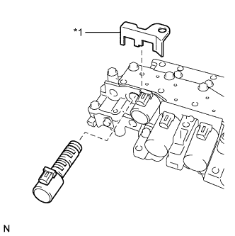
Coat shift solenoid valve SL4 and the bolt with ATF.
-
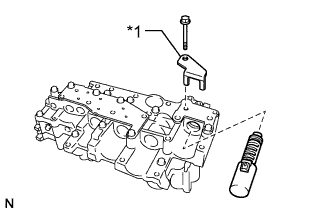
Text in Illustration *1 Lock Plate Install shift solenoid valve SL4 to the valve body with the lock plate and bolt.
- Torque:
- 11 N*m { 110 kgf*cm, 8 ft.*lbf }
-
-
INSTALL SHIFT SOLENOID VALVE SL3
-
Coat shift solenoid valve SL3 and the bolt with ATF.
-
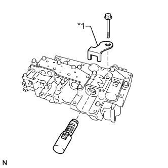
Text in Illustration *1 Lock Plate Install shift solenoid valve SL3 to the valve body with the lock plate and bolt.
- Torque:
- 11 N*m { 110 kgf*cm, 8 ft.*lbf }
-
-
INSTALL SHIFT SOLENOID VALVE SL1
-
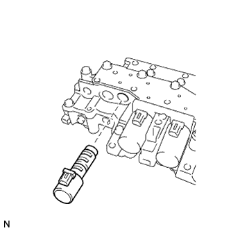
Coat shift solenoid valve SL1 with ATF.
-
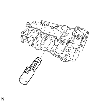
Install shift solenoid valve SL1 to the valve body.
-
-
INSTALL SHIFT SOLENOID VALVE SL2
-
Coat shift solenoid valve SL2 and the bolt with ATF.
-
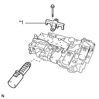
Text in Illustration *1 Lock Plate Install shift solenoid valve SL2 to the valve body with the lock plate and bolt.
- Torque:
- 11 N*m { 110 kgf*cm, 8 ft.*lbf }
-
-
INSTALL SHIFT SOLENOID VALVE SLU
-
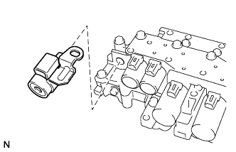
Coat shift solenoid valve SLU with ATF.
-
Install shift solenoid valve SLU to the valve body.
-
-
INSTALL SHIFT SOLENOID VALVE SLT
-
Coat shift solenoid valve SLT with ATF.
-
Text in Illustration *1 Lock Plate Install shift solenoid valve SLT and the lock plate to the valve body.
-
-
INSTALL SHIFT SOLENOID VALVE SL
-
Coat shift solenoid valve SL with ATF.
-
Install shift solenoid valve SL to the valve body.
-
-
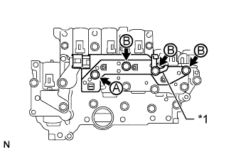
INSTALL ATF TEMPERATURE SENSOR
-
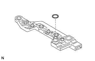
Coat a new O-ring with ATF and install it to the ATF temperature sensor.
-
Coat the 4 bolts with ATF.
-
Install the ATF temperature sensor and clamp to the valve body with the 4 bolts.
- Torque:
- 11 N*m { 110 kgf*cm, 8 ft.*lbf }
Text in Illustration *1 Clamp Tech Tips
Each bolt length is indicated below.
Bolt A: 25 mm (0.984 in.)
Bolt B: 85 mm (3.35 in.)
-
-
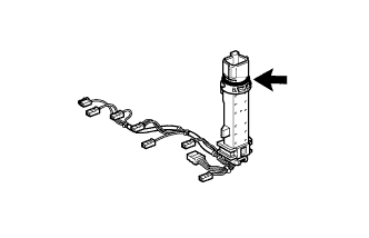
INSTALL TRANSMISSION WIRE
-
Coat the O-ring of the transmission wire connector with ATF.
-
Coat the bolt with ATF.
-
Install the transmission wire to the valve body with the lock plate and bolt.
- Torque:
- 11 N*m { 110 kgf*cm, 8 ft.*lbf }
-
Attach the transmission wire to the wire harness clamp and connect the 9 connectors.
-